Distributed resonant clock grid synthesis

a technology of distributed resonant clocks and clock distribution networks, applied in the direction of generating/distributing signals, instruments, program control, etc., can solve the problems of increasing failure rates, power consumption, and preventing the synthesis of clocks, and achieve the effect of significant power savings in the resulting devices

Active Publication Date: 2014-05-06
RGT UNIV OF CALIFORNIA
View PDF2 Cites 3 Cited by
  • Summary
  • Abstract
  • Description
  • Claims
  • Application Information

AI Technical Summary

Benefits of technology

[0020]The principles of the present invention provide for techniques for implementing LC resonant tank networks that minimize clock skew and power with minimum inductor area overhead by implementing suitable LC tank placement, sizing and driver buffering.
[0022]The initial grid and input grid buffer 52 are implemented using a standard clock grid methodology. However, placing and sizing LC tanks 50 on the clock grids 52 and buffer re-sizing methods are implemented according to algorithms described below. The principles of the present invention enable the locating, placing, and sizing procedures to be fully automated while also enabling extremely significant power savings in the resulting devices.

Problems solved by technology

One serious impediment to achieving what is demanded from VLSI devices is power consumption.
But, more power produces more heat, which increases failure rates.
Consequently, power consumption is the predominant challenge in improving modern high performance systems.
Unfortunately, as clock rates and VLSI chip densities increase it becomes very difficult to ensure that all of the chips can keep up with the clocks.
Different lengths coupled with unavoidable signal delays caused by distributed resistances and capacitances mean that clock signals arrive at different devices at different times (clock skew).
Such can effectively limit the performance of a VLSI chip.
Compounding the clocking problems is the fact that clocking requires power.
In fact, the on-chip clock distribution network (CDN) of modern VLSI chips often consumes more than 35% of the total chip power and can occasionally require as much as 70%.
While very promising in theory, VSLI resonant clock networks are seldom used, usually being restricted to VLSI clock distribution networks that use H-trees.
While conceptually interesting, VLSI resonant clock distribution networks are seldom if ever used.
A major problem is that prior art resonant clock distribution networks required even (balanced) distribution of gates, terminals, loads, distributed capacitance and inductances and conductors.
Uneven loading of resonant clock distribution networks significantly alters resonant behavior and can prevent correct functionality of LC tanks.
Such limitations are neither practical nor realistic in actual VLSI designs.
However, resonant clock grids present several unique challenges to automated designs compared to fully buffered grids.
First, the parasitic resistances and inductances in a clock distribution alter the resonant frequency.
Second, the resistances add attenuation at high frequencies.
Third, the unsymmetrical structure of clock network and unbalanced load require precious inductor sizing.
Such factors all lead to altered resonant frequencies and phase conflicts.
No successful prior art method to address those problems has been implemented.

Method used


Image

  • Distributed resonant clock grid synthesis
  • Distributed resonant clock grid synthesis
  • Distributed resonant clock grid synthesis

Examples


Embodiment Construction

[0031]The presently disclosed subject matter now will be described more fully hereinafter with reference to the accompanying drawings in which one embodiment is shown. However, it should be understood that this invention may take many different forms and thus should not be construed as being limited to the embodiment set forth herein.

[0032]All publications mentioned herein are incorporated by reference for all purposes to the extent allowable by law. In addition, in the figures, identical numbers refer to like elements throughout. Additionally, the terms “a” and “an” as used herein do not denote a limitation of quantity, but rather denote the presence of at least one of the referenced items.

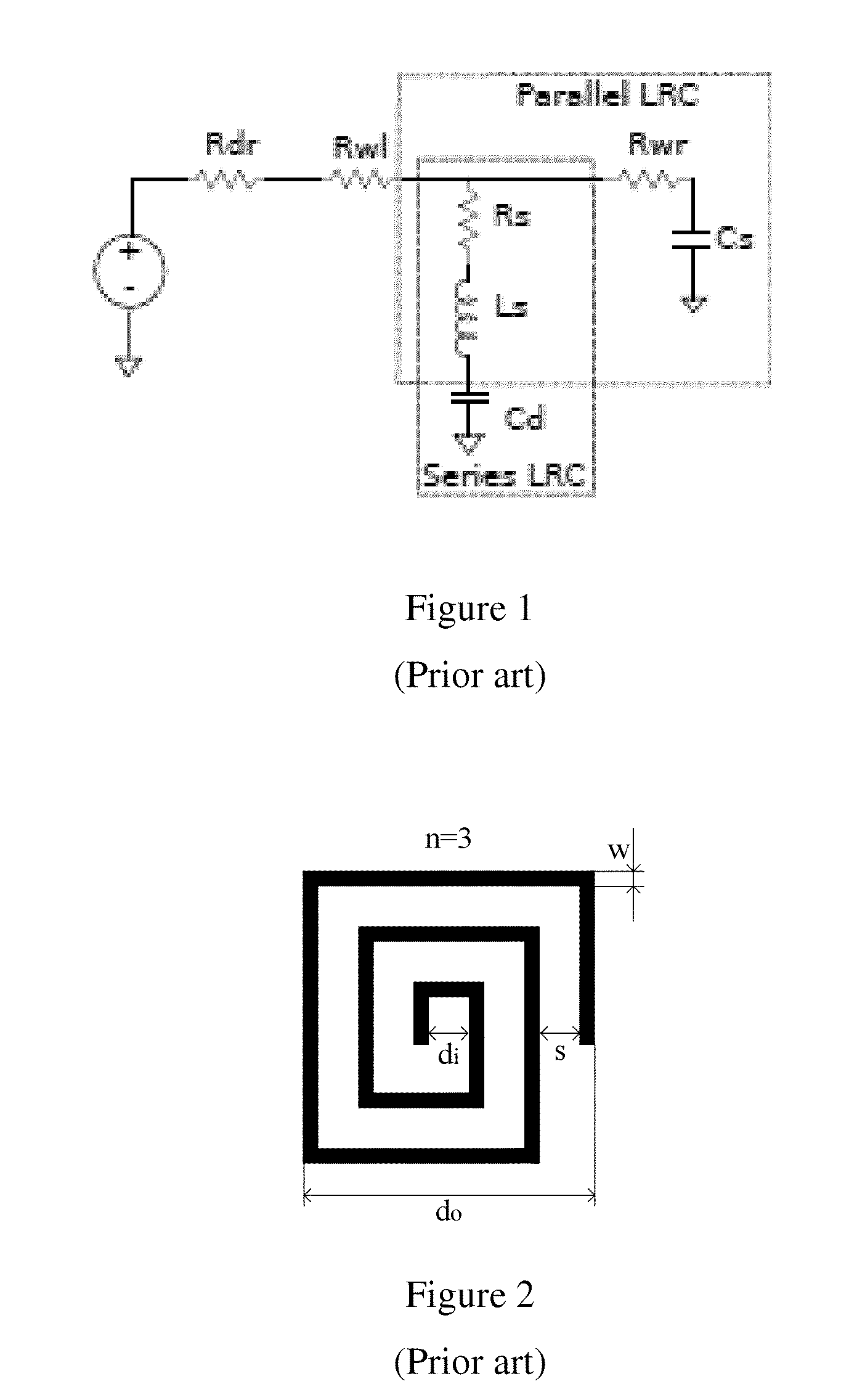
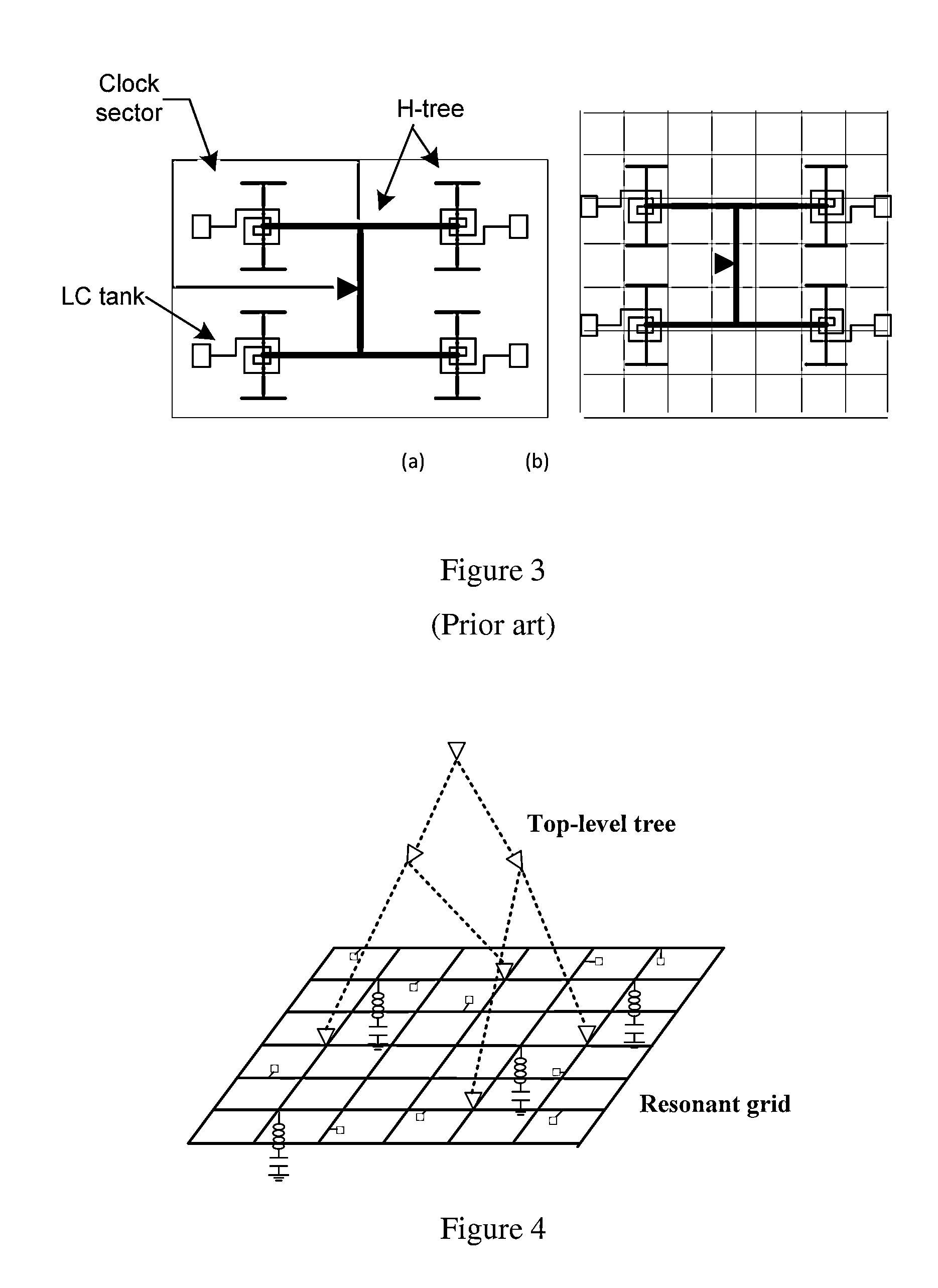
[0033]As previously described, parasitic resistances of clock networks shift their resonant frequency and cause attenuated voltage swings that can result in malfunction of logic circuit. The currents that pass through an LC tank 10, 50 (see FIGS. 1 and 4) can be very large at resonant frequency. ...


PUM


Abstract

A method of implementing a VLSI clock network is implemented. That method includes a step of generating an initial VLSI clock grid for incorporation on a silicon die. An input grid buffer is then sized and implemented for the VLSI clock grid. LC tanks are then placed and sized in the VLSI clock grid to implement a resonant tank clock grid and the input grid buffer is resized. A check of the resonant tank design criteria is then made. If the design criteria are met the resonant VLSI clock grid with its LC tanks is implemented. If not, another attempt at implementing a suitable LC tanks placement and sizing is made. The process iterates until a VLSI clock grid that meets the design criteria is obtained.

Description

RELATIONSHIP TO OTHER APPLICATIONS[0001]To the extent allowed by law this application claims priority to and the benefit of U.S. provisional application No. 61 / 502,626 entitled “DISTRIBUTED RESONANT CLOCK GRID SYNTHESIS” filed on Jun. 29, 2011 having inventors Dr. Matthew Guthaus and Xuchu Hu. That application is hereby incorporated by reference to the fullest extent allowed by law.FIELD OF THE INVENTION[0002]The presently disclosed subject matter is directed towards the synthesis of clock distribution networks that use distributed inductor-capacitor (LC) tanks with asymmetric clock loads.BACKGROUND OF THE INVENTION[0003]The on-going demand for high performance electronic systems has driven the need for high-speed digital Very Large Scale Integration (VLSI) chips. VLSI implementations have proceeded in two inter-related directions: higher performance and higher density (more devices per unit area). While modern VLSI chips have achieved astonishingly high levels of performance and ch...

Claims


Application Information

Patent Timeline
Patent Type & Authority Patents(United States)
IPC IPC(8): G06F17/50G06F9/455
CPCH01L25/00H01L2924/0002G06F2217/62G06F17/5072G06F1/10G06F30/396H01L2924/00G06F30/392
Inventor GUTHAUS, MATTHEWHU, XUCHU
Owner RGT UNIV OF CALIFORNIA
Why Eureka
Try Eureka