Work apparatus having an electric drive motor

a technology of electric drive motor and work apparatus, which is applied in the direction of electric controller, dynamo-electric converter control, instruments, etc., can solve the problems of difficulty for the operator to start and hold a suitable working area, and achieve the effect of simple manner and good efficiency

Active Publication Date: 2014-05-13
ANDREAS STIHL AG & CO KG
View PDF14 Cites 6 Cited by
  • Summary
  • Abstract
  • Description
  • Claims
  • Application Information

AI Technical Summary

Benefits of technology

[0005]It is an object of the invention to provide a work apparatus having an electric drive motor configured so that an operator can start and during operation securely hold a working region with a good efficiency in a simple manner.
[0008]The configuration of the control characteristic line in this manner leads to a working region which the operator can easily approach. The working region A can be easily approached and held by the operator over a predetermined rotational speed band because of the diametrically opposite behavior of mean power and torque. The configuration of the working region is, thereby, selected so that the electric motor used is operated with a good to optimal efficiency.
[0011]For providing a significant working region, it is advantageous when the electrical input power of the electric drive motor drops slightly in the predetermined rotational speed band especially from a maximum value by approximately 15% to 30%, preferably approximately 18%. Thus, a wider, more easily approachable working region having a high electrical efficiency results.
[0015]Advantageously, the cutting power plateau is configured with little slope. The cutting power plateau preferably drops with increasing thrust force. The experienced operator will easily find an operating point on the cutting power plateau because a larger thrust force leads to a significantly dropping cutting power. The operator will consequentially again reduce the thrust force so that the operating point is shifted on the cutting power plateau up to a maximum power in the area of the beginning of the cutting power plateau in the transition to the unchanged cutting power curve. If the operator further increases the thrust force notwithstanding lightly decreasing cutting power, the operating point at the end of the cutting power plateau wanders to the falling curve segment or transitions to a receding curve segment of the adjusted power curve whereby the machine significantly loses cutting power which leads to a corresponding counter reaction by the operator. The receding curve segment has an approximately even gradient as the branch of the curve of the unchanged power curve which slopes upwards to the cutting power plateau. By lowering the thrust force, the operator leads the operating point back onto the cutting power plateau of the cutting curve. The operator can at any time go to one or the other end of the cutting power plateau via the control of the thrust force. In a simple manner, the operator will be led to an operation of the work apparatus in a region of the cutting power plateau because of the predetermined control characteristic line of the control unit, which leads to an optimal cutting power.
[0016]A predetermined rotational speed band of the working region of a work tool is in a bandwidth of 500 to 2000 revolutions per minute, preferably around 1000 revolutions per minute. A characteristic line segment, which extends from the upper rotational speed end of the pregiven rotational speed band, drops off steeply toward zero over a narrow rotational speed band of a few hundred revolutions per minute. Preferably, the narrow rotational speed band spans approximately 200 revolutions per minute. The steepness of the characteristic line segment quickly leads to a high torque and a correspondingly high cutting power when cutting is started at maximum rotational speed, so that an operating point in the area of the cutting power plateau can be quickly and reliably started. The output rotational speed to the work tool can be the rotational speed of the electric motor directly driving the work tool or the rotational speed of a gear output shaft which drives the work tool in an adapted manner.
[0018]Furthermore, as a result of the operation of the work tool having an operating point in the region of the cutting power plateau it is ensured that the rotational speed of the drive motor is always in a region which ensures sufficient cooling of the drive motor. Thus, the operator drives the work tool not only in an optimal cutting power range but also in a thermally balanced operating region near the thermal constant power output limit which excludes thermal damaging of the electric drive unit even during constant operation. Advantageously, the consumed electrical input power of the drive motor during constant operation is set to approximately 25% over the input power determined by the thermal constant power output limit.

Problems solved by technology

Because of the typical characteristic curve course of the electric motor, it is difficult for the operator to start and hold a suitable working region with good efficiency by controlling the thrust force.

Method used


Image

  • Work apparatus having an electric drive motor
  • Work apparatus having an electric drive motor
  • Work apparatus having an electric drive motor

Examples


Embodiment Construction

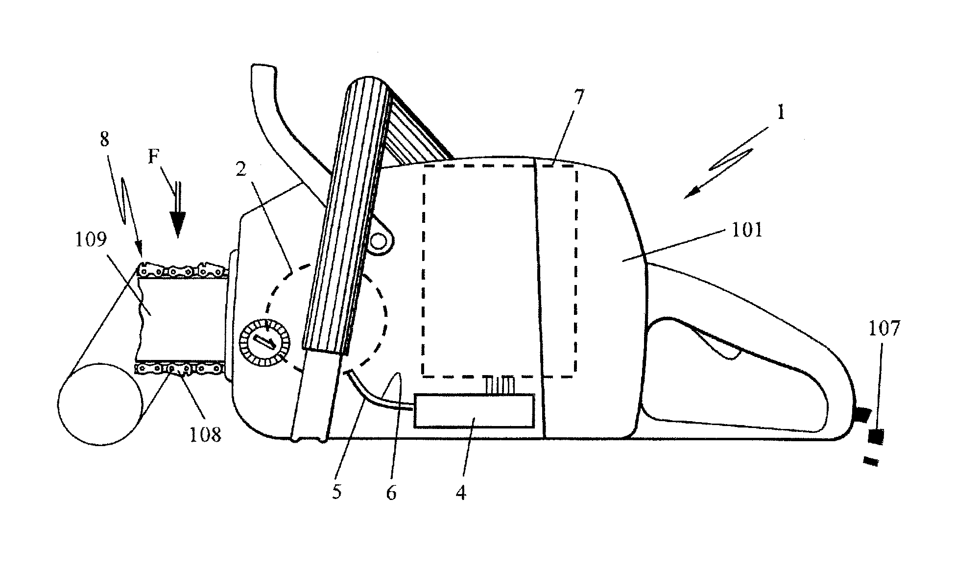
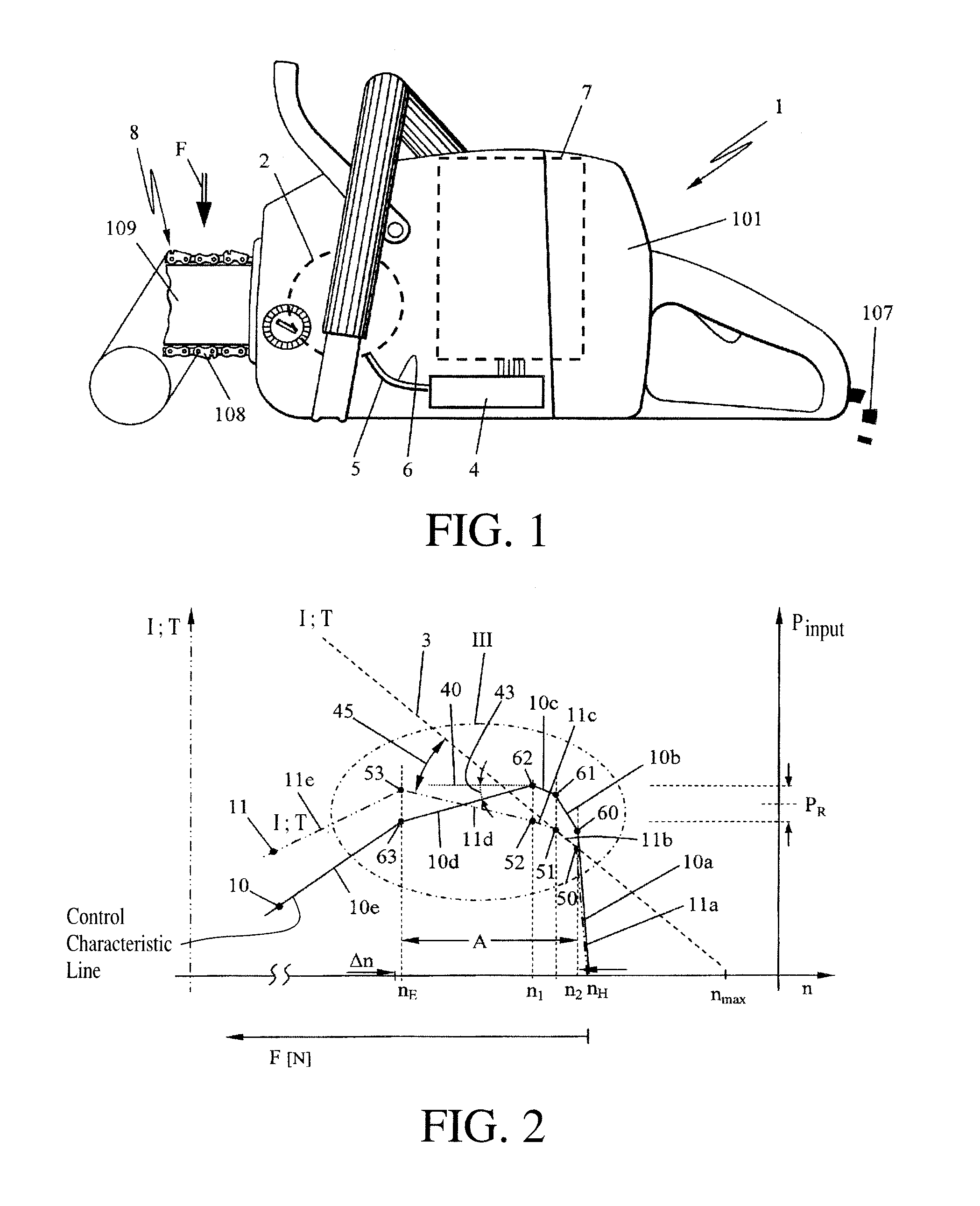
[0027]The invention generally relates to an electric, handheld work apparatus 1 having a driven work tool 8. In FIG. 1, a chain saw 101 is shown as an example of such a work apparatus 1 whose electric drive motor 2 drives the work tool 8—in the embodiment a saw chain 108—with a motor-specific characteristic line 3 (FIG. 2) of the consumed engine current I over the rotational speed n. This motor-specific characteristic line 3 at the same time approximately represents the characteristic course of the torque T outputted by the electric motor 2 over the rotational speed n. Thereby, at maximum idling rotational speed nmax the torque T at the output shaft approaches zero, while the current I drops to an assigned idling current. Hereafter, the characteristic line 3 is to approximately represent the motor current I over the rotational speed n as well as the torque T over the rotational speed n. In the embodiment, the characteristic line 3 is shown essentially linearly; other characteristic ...


PUM


Abstract

An electric chain saw has an electric drive motor defining a motor-specific characteristic line of the drawn-in current as a function of the rotational speed of the motor. A control unit controls the current flowing through the drive motor below an engaging rotational speed to values below the motor-specific characteristic line. In order to generate an operating point the operator can feel in a working region in a predetermined rotational speed band, a control characteristic line of the electric input power of the electric drive motor as a function of the rotational speed is provided above the engaging rotational speed. The control characteristic line is adapted to reduce the electric input power within the rotational speed band to an approximately even mean power so as to cause the torque of the drive motor to increase within the rotational speed band with falling rotational speed.

Description

CROSS REFERENCE TO RELATED APPLICATION[0001]This application claims priority of German patent application no. 10 2010 047 761.3, filed Oct. 8, 2010, the entire content of which is incorporated herein by reference.FIELD OF THE INVENTION[0002]The invention relates to a handheld work apparatus having an electric drive motor, in particular to an electric chain saw.BACKGROUND OF THE INVENTION[0003]U.S. Pat. No. 7,652,438 discloses a handheld work apparatus, for example a chain saw, whose electric drive motor has a motor-specific characteristic line of the drawn-in electric current versus the rotational speed. Electrical power is supplied to the electric drive motor via a control unit. Below a selected minimum rotational speed (engagement speed r), the current flowing through the electric drive motor is limited to values which are below the motor-specific characteristic line. Thus, a general limiting of the current consumption of the electric motor is supposed to be done, in order to achi...

Claims


Application Information

Patent Timeline
Patent Type & Authority Patents(United States)
IPC IPC(8): H02K7/14
CPCH02P23/0081H02P23/26
Inventor ROSSKAMP, HEIKOLIEBHARD, GERNOTWICHERT, RENE
Owner ANDREAS STIHL AG & CO KG
Why Eureka
Try Eureka