Dynamic driver circuit

a driver circuit and dynamic technology, applied in the field of integrated circuits, can solve the problems of limiting the speed of switching for the word line driver, the critical speed of the read mode of many memory devices, etc., and achieve the effect of improving the switching characteristics without a significant cost and increasing the circuit complexity

Active Publication Date: 2014-05-13
MACRONIX INT CO LTD
View PDF1 Cites 7 Cited by
  • Summary
  • Abstract
  • Description
  • Claims
  • Application Information

AI Technical Summary

Benefits of technology

[0006]Driver circuitry is described which can be used in low voltage, high speed circuit environments for driving high capacitive loads. The driver can include a dynamic selection circuit that sets a control node of the driver. The dynamic selection circuit includes a pull-up circuit and a pull-down circuit responsive to decoded control signals, along with a pull-up boost circuit. The pull-up boost circuit is controlled to boost current flow upon a transition of the voltage at the control node. The driver is suitable for use as a word line driver in low supply voltage integrated circuit memory devices. The driver can improve switching characteristics without a significant cost in increased circuit complexity.
[0007]A circuit usable as a word line driver that is described herein, includes a driver that switches in response to a voltage on a control node, and a circuit supplying a voltage to the control node. The circuit that supplies a voltage to a control node provides a first static current tending to pull the control node up to a first source voltage, and provides a fighting current pulse in response to a signal selecting the driver to pull the control node down to a second source voltage, overcoming the first static current. In addition, a circuit provides a pull-up boost current on a transition of the signal selecting the driver that turns off the fighting current, and applies a boosting current pulse to the control node to assist pulling the control node quickly to the first source voltage. This boosting current pulse can be applied without requiring feedback from the load.

Problems solved by technology

The read mode for many memory devices is often speed critical.
However, low voltages that depend on the supply voltage used by the peripheral circuits, including word line decoders and driver selection circuits, can limit the speed of switching for the word line drivers.

Method used


Image

  • Dynamic driver circuit
  • Dynamic driver circuit
  • Dynamic driver circuit

Examples


Embodiment Construction

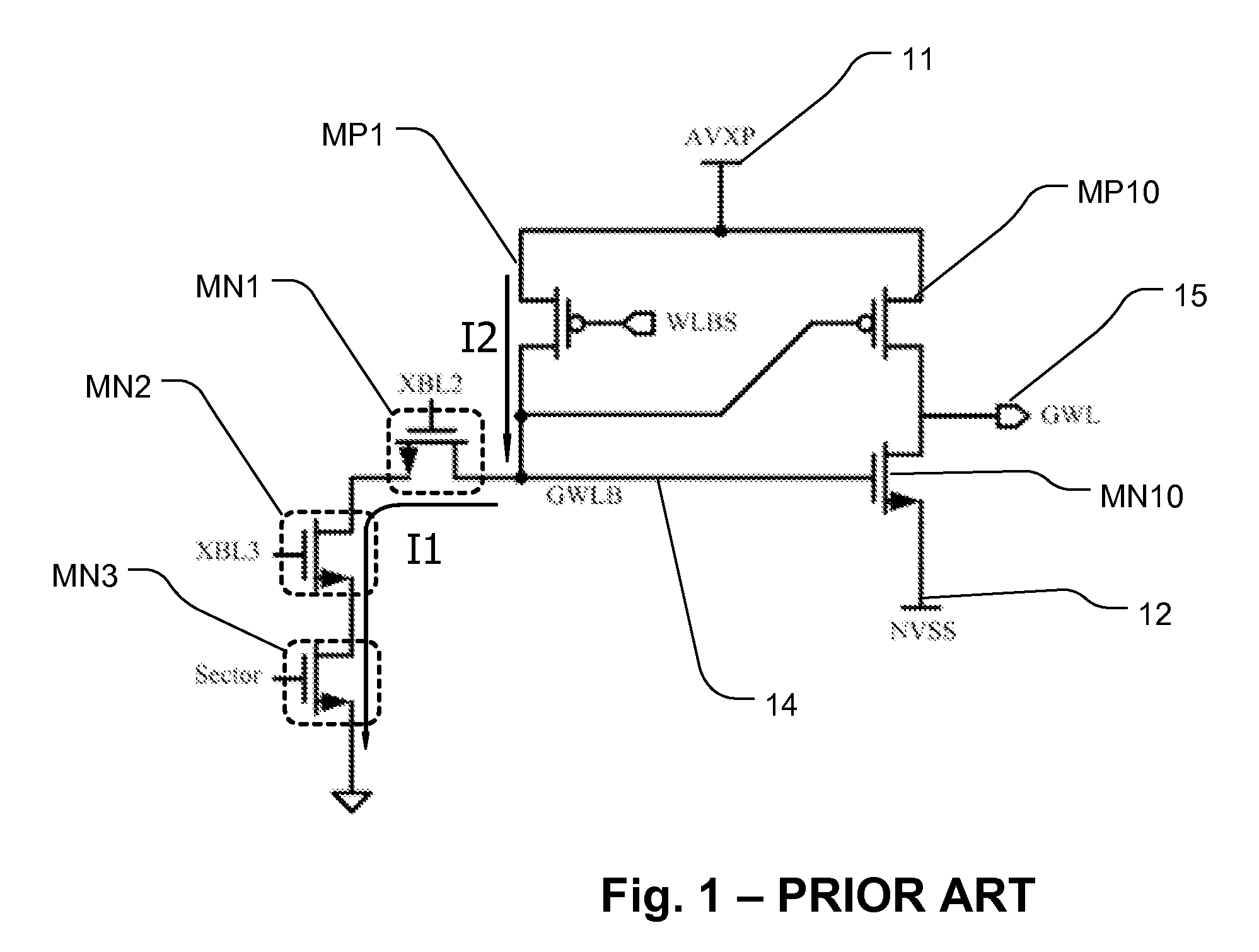
[0015]FIG. 1 shows a circuit diagram of word line driver and driver selection circuit which can be used in a low voltage integrated circuit, to drive a high voltage on a high capacitive load.

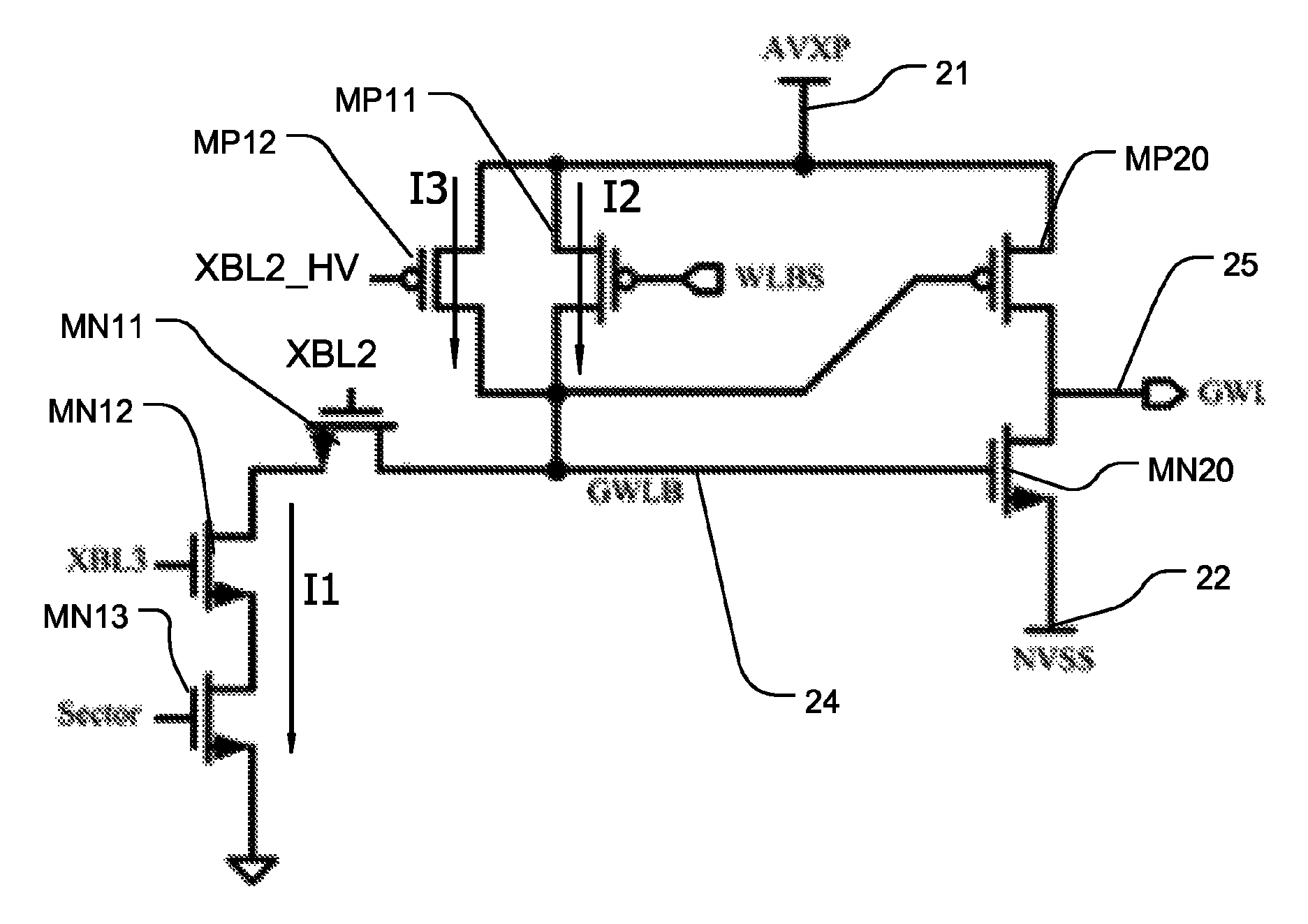
[0016]In this example, the driver includes p-channel transistor MP10 having a source connected to a first source voltage AVXP (from voltage source 11) and a drain connected to a load which comprises a global word line 15 for an integrated circuit memory. Also, an n-channel transistor MN10 has a drain connected to the global word line 15, and a source connected to a second source voltage NVSS (from voltage source 12). The source and drain can be referred to as current carrying terminals of the transistors. The gates of transistors MP10 and MN10 are connected together to a driver control node 14, at which the voltage GWLB occurs. Thus, the transistors MP10 and MN10 are connected in the form of an inverting buffer, delivering a high voltage AVXP on the global word line 15 when the voltage GWLB is l...


PUM


Abstract

A circuit usable as a word line driver includes a driver that switches in response to a voltage on a control node, and a circuit supplying a voltage to the control node. The circuit that applies a voltage to control node provides a first static current tending to pull the control node up to a first source voltage, and provides a fighting current pulse in response to a signal selecting the driver to pull the control node down to a second source voltage, overcoming the first static current. In addition, a circuit provides a pull-up boost current on a transition of the signal selecting the driver that turns off the fighting current, and applies a boosting current pulse to the control node to assist pulling the control node quickly to the first source voltage.

Description

BACKGROUND[0001]1. Field of the Invention[0002]The technology relates to integrated circuits that include drivers for large loads, and in particular to word line drivers for low voltage memory devices.[0003]2. Description of Related Art[0004]Memory integrated circuits access memory cells with word lines powered by word line drivers, capable of driving various voltages at high speed on a large capacitive load. Word line drivers drive associated word lines with various voltage levels that depend on the mode of operation of the memory, where modes for a flash memory can include read, program, and erase operational modes. The voltages used for the various operating modes are often larger than the power supply voltages used for low voltage devices. For example, a word line voltage for a read operation in a flash memory may be about 5 volts, while the supply voltage for the device may be 1.8 volts.[0005]The read mode for many memory devices is often speed critical. However, low voltages t...

Claims


Application Information

Patent Timeline
Patent Type & Authority Patents(United States)
IPC IPC(8): H03B1/00H03K3/00
CPCG11C11/00G11C8/00G11C8/08G11C16/08
Inventor CHEN, CHANG-TINGCHANG, CHIN-HUNGYANG, SHANG-CHILU, KUAN-MINGCHEN, KEN-HUICHANG, KUEN-LONGHUNG, CHUN-HSIUNG
Owner MACRONIX INT CO LTD
Why Eureka
Try Eureka