Focal plane coding for digital imaging

a digital imaging and optical plane technology, applied in the field of optical plane coding for digital imaging, can solve the problems of limited ability to enhance imaging, post-processors cannot process information that has not been captured, and increase optical performance often means, so as to improve resolution and data efficiency, reduce thickness, and maintain resolution

Inactive Publication Date: 2014-05-13
DUKE UNIV +1
View PDF36 Cites 4 Cited by
  • Summary
  • Abstract
  • Description
  • Claims
  • Application Information

AI Technical Summary

Benefits of technology

[0007]It is a feature of an embodiment of the present invention to provide an imaging system having sub-pixel resolution. It is another feature of an embodiment of the present invention to provide multiplexing while still analyzing a true image. It is another feature of an embodiment of the present invention to provide imaging systems of reduced thickness while maintaining resolution and / or to improve resolution and data efficiency.

Problems solved by technology

However, there are limits on the ability to enhance imaging by simply increasing the density of pixels.
Further, post-processors cannot process information that has not been captured by the imaging system.
Additionally, increased optical performance often means increased complexity.
However, this blurring does not exploit the point of high field entropy of the system.

Method used


Image

  • Focal plane coding for digital imaging
  • Focal plane coding for digital imaging
  • Focal plane coding for digital imaging

Examples


Embodiment Construction

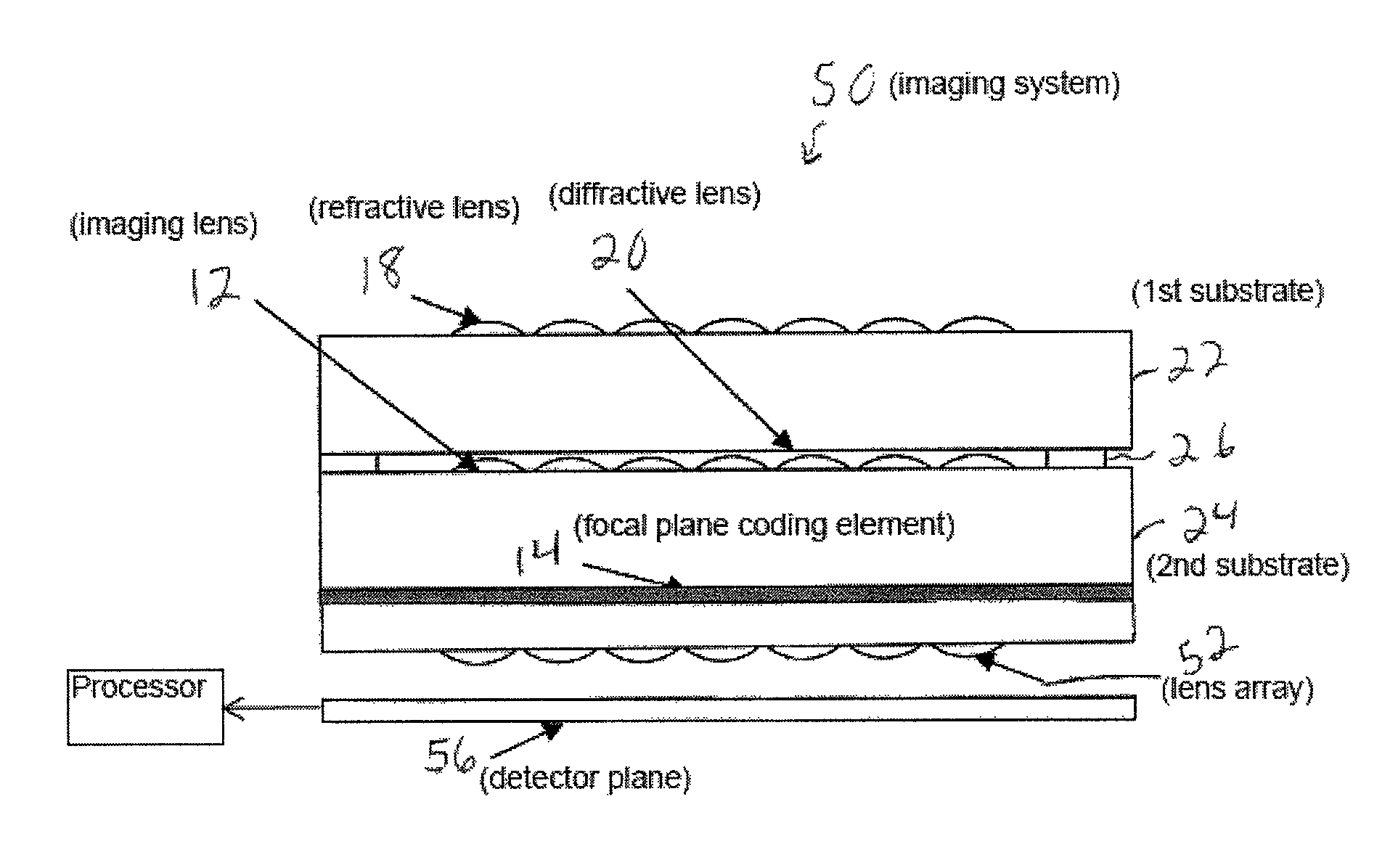
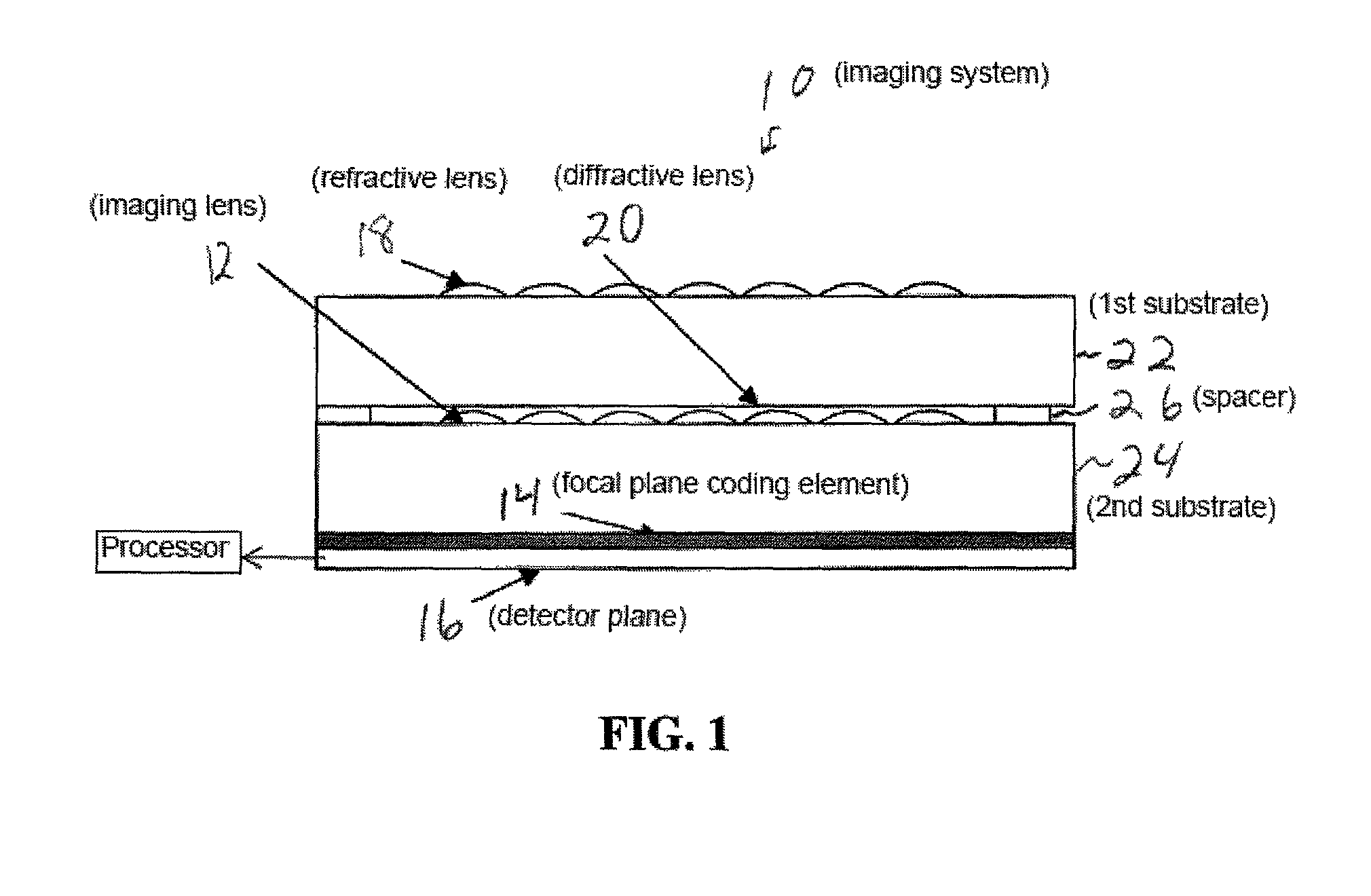
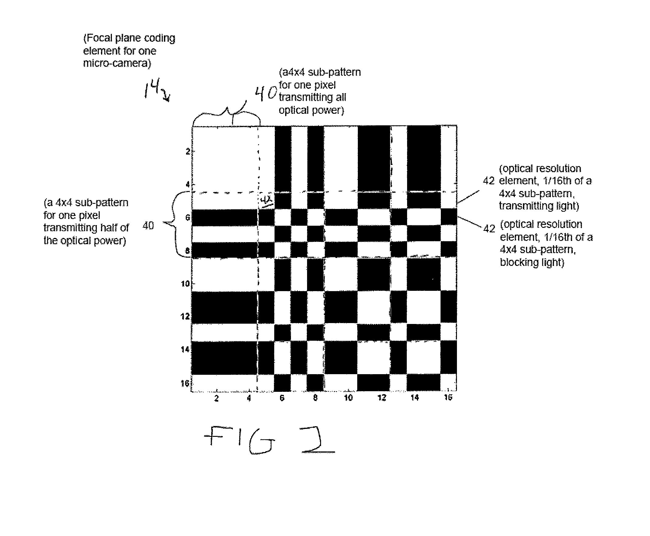
[0018]U.S. Provisional Application Ser. No. 60 / 538,506 filed Jan. 26, 2004 and entitled “Focal Plane Coding for Digital Imaging” is herein incorporated by reference in its entirety for all purposes.

[0019]The present invention will now be described more fully hereinafter with reference to the accompanying drawings, in which preferred embodiments of the invention are shown. The invention may, however, be embodied in different forms and should not be construed as limited to the embodiments set forth herein. Rather, these embodiments are provided so that this disclosure will be thorough and complete, and will fully convey the concept of the invention to those skilled in the art. In the drawings, the thickness of layers and regions are exaggerated for clarity. It will also be understood that when a layer is referred to as being “on” another layer or substrate, it may be directly on the other layer or substrate, or intervening layers may also be present. Further, it will be understood tha...


PUM


Abstract

An imaging system includes an array of lenses, a plurality of sensor pixels for each lens, the sensor pixels being on an image plane of the imaging system, and a corresponding plurality of focal plane coding elements. A focal plane coding element for each sensor pixel has multiple sub-pixel resolution elements. The focal plane coding element being between the lens and each sensor pixel, wherein sub-pixel resolution elements over the plurality of focal plane coding elements represent a selected transform matrix having a non-zero determinant. The output of the plurality of sensor pixels being an image multiplied by this matrix.

Description

CROSS-REFERENCE TO RELATED APPLICATION[0001]The present application claims priority under 35 U.S.C. §119(e) U.S. Provisional Application Ser. No. 60 / 538,506 filed Jan. 26, 2004 and entitled “focal Plane Coding for Digital Imaging” which is incorporated herein by reference in its entirety.BACKGROUND[0002]Imaging system design begins with the focal plane. Assume the focal plane has pixels of a size p, with a size of the image on the focal plane being d. The number n of pixels is n=d / p. The N.A. or numerical aperture roughly determines the field of view of the system, and is defined as N.A.=n0 sin θ, where n0 is the refractive index of the medium through which the light has traveled. Assuming the medium is air and the small angle approximation is valid, n0≈1, so N.A.=sin θ. The angular resolution is Δθp=p / f due to the focal plane and Δθλ=λ / d due to the diffraction limit. Since f and d are related by the N.A., Δθp / Δθλ=N.A.p / λ. Thus, for a given focal plane, the angular resolution is inv...

Claims


Application Information

Patent Timeline
Patent Type & Authority Patents(United States)
IPC IPC(8): H04N9/07H04N5/225
CPCH04N3/1587H04N5/2254H04N25/48
Inventor BRADY, DAVIDFELDMAN, MICHAEL DPITSIANIS, NIKOS P.
Owner DUKE UNIV
Why Eureka
Try Eureka