Energy-efficient building structure having a dynamic thermal enclosure

a dynamic thermal enclosure and building structure technology, applied in ventilation systems, lighting and heating apparatus, heating types, etc., can solve problems such as damage to interior finishes, difficulty in implementation, and discomfort of occupants from heat and glare, so as to facilitate the removal of warm air, improve thermal performance, and improve insulation

Active Publication Date: 2014-05-20
STEVENS KIRK RUSSELL +4
View PDF29 Cites 35 Cited by
  • Summary
  • Abstract
  • Description
  • Claims
  • Application Information

AI Technical Summary

Benefits of technology

[0012]Accordingly, the present invention is directed to an energy-efficient building structure having a dynamic thermal enclosure that substantially obviates one or more problems resulting from the limitations and deficiencies of the related art.
[0013]The preferred embodiments of the present invention provide a constructed space that serves as an insulating layer for habitable spaces, an air displacement mechanism that facilitates the removal of warm air from the habitable interior and a structure that provides preheated air to a forced air heating system via solar radiantly heated ductwork. The insulating layer where one preferred embodiment provides a location in a space at the top of a building traditionally referred to as an “attic” provides an insulated roof plane, insulated wall plane, an insulated floor plane and the insulating contained air space. Acting as a single unit the insulating planes and space provide superior insulation when compared to structures where a single plane acts as a thermal barrier. The penetrations in the constructed space are comprised of remote controlled motorized high performance windows, skylights and dampers connected to louvers, control air movement in and out of the space drawing warm air from the interior and exhausting warm interior air to the exterior during periods when fresh outdoor air is desired. Preferably, the motorized remote cont...

Problems solved by technology

While a passive solar approach is beneficial, it is difficult to implement given the need for direct solar exposure on high heat mass materials and the need to control the heat released from the material.
There are issues of occupant discomfort from heat and glare in interior spaces with intense solar exposure.
The sun can also damage interior finishes.
Utilizing a passive solar approach to move heat between spaces horizontally or by providing walls that absorb solar heat tend to block views from the interior spaces and can, in certain situations, actually reduce interior light levels.
Energy efficient buildings that heat air sandwiched ...

Method used


Image

  • Energy-efficient building structure having a dynamic thermal enclosure
  • Energy-efficient building structure having a dynamic thermal enclosure
  • Energy-efficient building structure having a dynamic thermal enclosure

Examples


Embodiment Construction

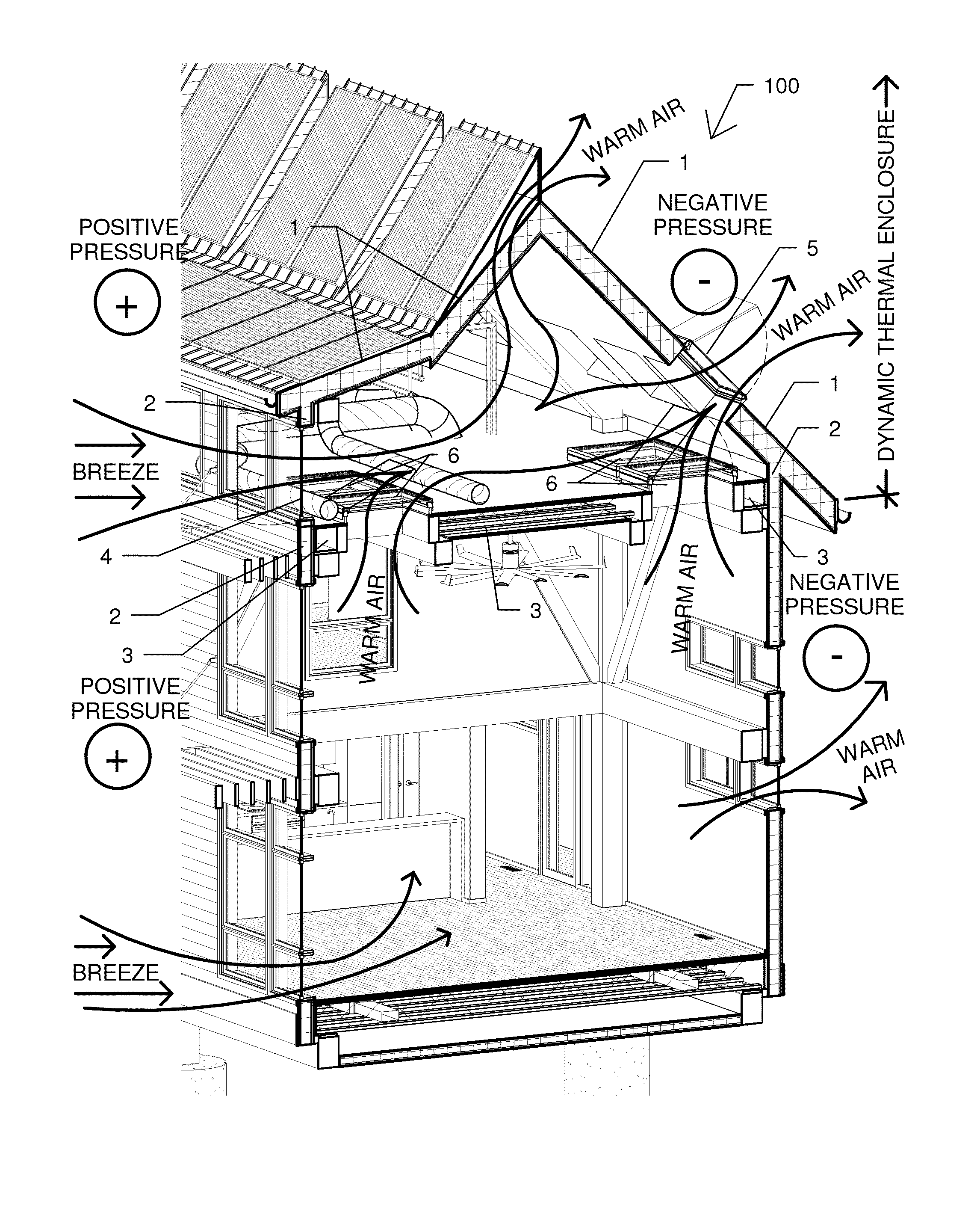
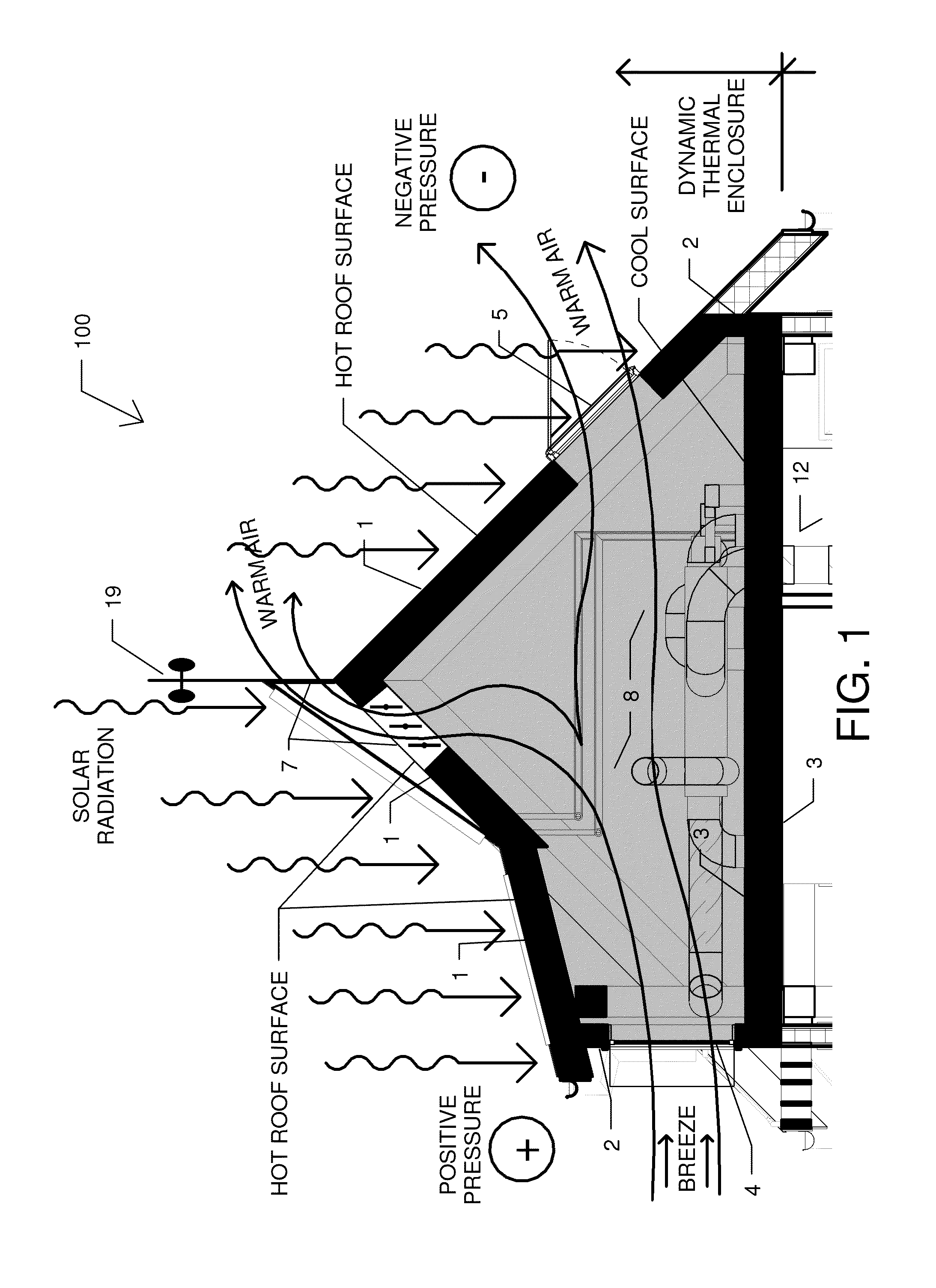
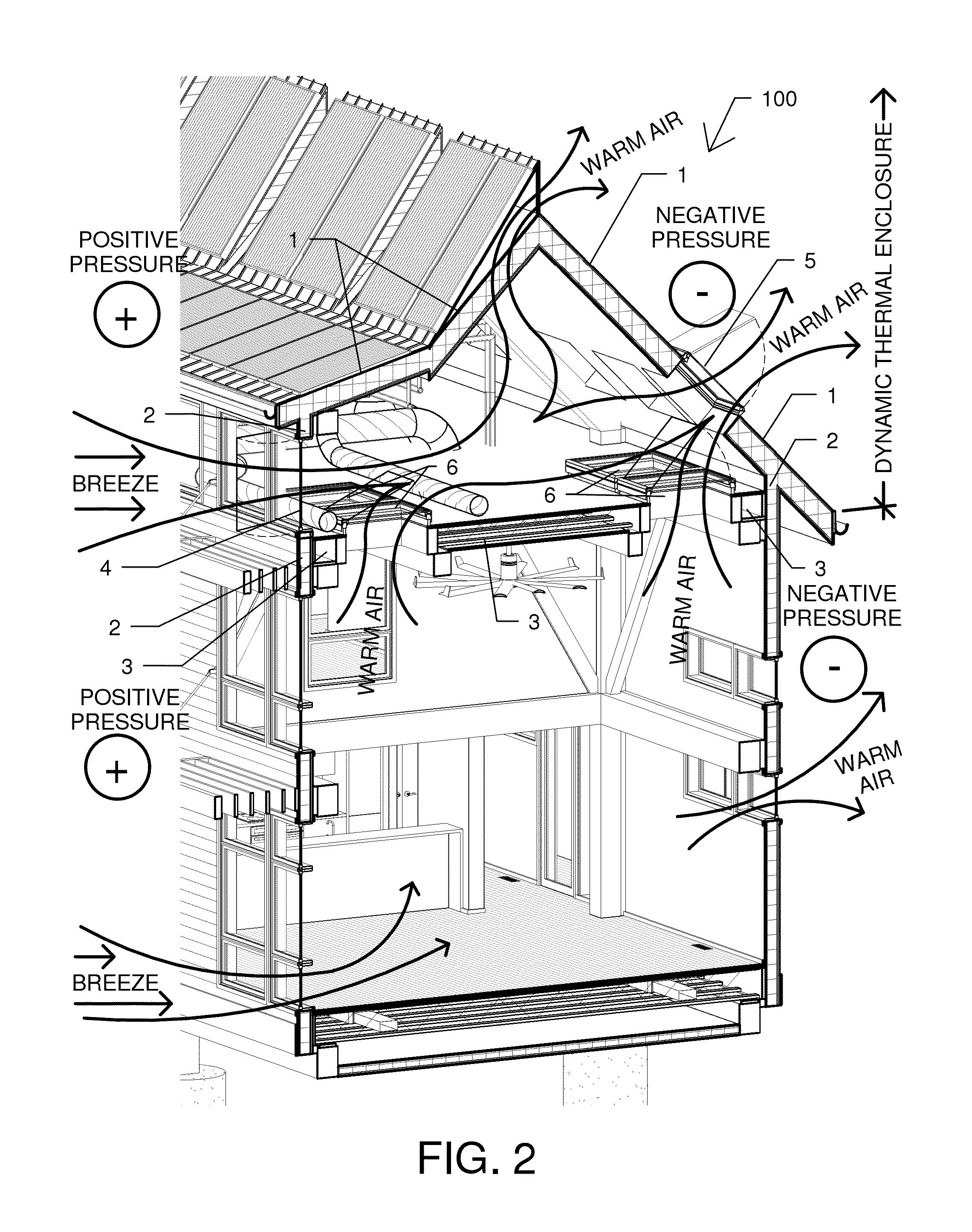
[0032]Referring to FIG. 1, the system 100 generally comprises the creation of an enclosure adjacent to a habitable building envelope for the primary purpose of aiding with the temperature conditioning of interior air. The enclosure which in this embodiment would be typically referred to as an “attic”, comprises outer insulating layers, in this embodiment being an insulated roof 1, insulated walls 2 and a layer between the enclosure and the habitable interior building spaces 12, being an insulated floor 3. Openings within these layers, in this embodiment being comprised of remote control insulating “attic” windows 4, roof skylights 5, “attic” floor mounted skylights 6 (see FIG. 2) and insulated dampers connected to louvers 7, provide thermal control of the space. In cooling periods, as illustrated in FIG. 1, the “attic” windows 4, roof skylights 5 and as needed insulated dampers connected to louvers 7 open to provide through air flow to keep the enclosed space 8 and “attic” floor lay...


PUM


Abstract

A constructed enclosure, adjacent to an interior habitable space, uses a microprocessor-based control unit to operate enclosure openings to provide a multi-layer insulation barrier containing or creating heat, or providing a radiant barrier, isolating by open air, a thermal insulating layer from warm exterior surfaces, maximizing insulation values. The enclosed space, through the use of openings, which in one embodiment are windows, skylights and dampers connected to louvers, is heated by radiant exposure or cooled by natural air flow or exhaust fan. Return air is heated upstream from a forced air heating unit by traversing ductwork heated by the enclosure and by direct solar exposure from enclosure windows. Enclosure openings to the habitable interior spaces create air displacement drawing warm air out of the interior and fresh air in through exterior windows. The energy efficient system is tailored for immediate climate specific conditions.

Description

CROSS-REFERENCE TO RELATED APPLICATIONS[0001]This patent application claims priority to, and incorporates by reference in its entirety, pending U.S. Provisional Patent Application No. 61 / 583,153, entitled “An Energy-Efficient Building Structure Having A Dynamic Thermal Enclosure”, filed on Jan. 4, 2012.STATEMENT REGARDING FEDERALLY SPONSORED RESEARCH OR DEVELOPMENT[0002]Not Applicable.NAMES OF THE PARTIES TO A JOINT RESEARCH AGREEMENT[0003]Not Applicable.INCORPORATION BY REFERENCE OF MATERIAL SUBMITTED ON A COMPACT DISK[0004]Not Applicable.BACKGROUND OF THE INVENTION[0005]1. Field of the Invention[0006]This invention relates generally to heating, cooling and ventilation systems for building structures, and more particularly, relates to the creation of an enclosure, which through the specific attributes of the envelope, aids with the space conditioning of the interior habitable spaces.[0007]2. Background and Description of Related Art[0008]There are buildings with roof systems which ...

Claims


Application Information

Patent Timeline
IPC IPC(8): E04D13/18F24F11/00E04B1/70F24F7/00
CPCY02B10/20F24F11/00E04B1/70F24D5/005F24D5/04F24F2007/004E04B1/74F24F2011/0006F24D19/1093F24F11/0001F24F7/00F24F2005/0064F24D5/12Y02B10/24F24F2011/0002Y02A30/272Y02B30/13
Inventor STEVENS, KIRK RUSSELLSTEVENS, SHERYL O'REILLYSTEVENS, KELSEY O'REILLYO'REILLY, JR., PATRICK FRANCISO'REILLY, III, PATRICK FRANCIS
Owner STEVENS KIRK RUSSELL
Why Eureka
Try Eureka