
Turbomachine

a technology of turbines and bearings, applied in the direction of machines/engines, mechanical devices, liquid fuel engines, etc., can solve the problems of preventing oil leakage from the central bearing housing into the turbine housing, and achieving an effective sealing system

Active Publication Date: 2014-05-20
CUMMINS TURBO TECH
View PDF9 Cites 2 Cited by
  • Summary
  • Abstract
  • Description
  • Claims
  • Application Information

AI Technical Summary

Benefits of technology

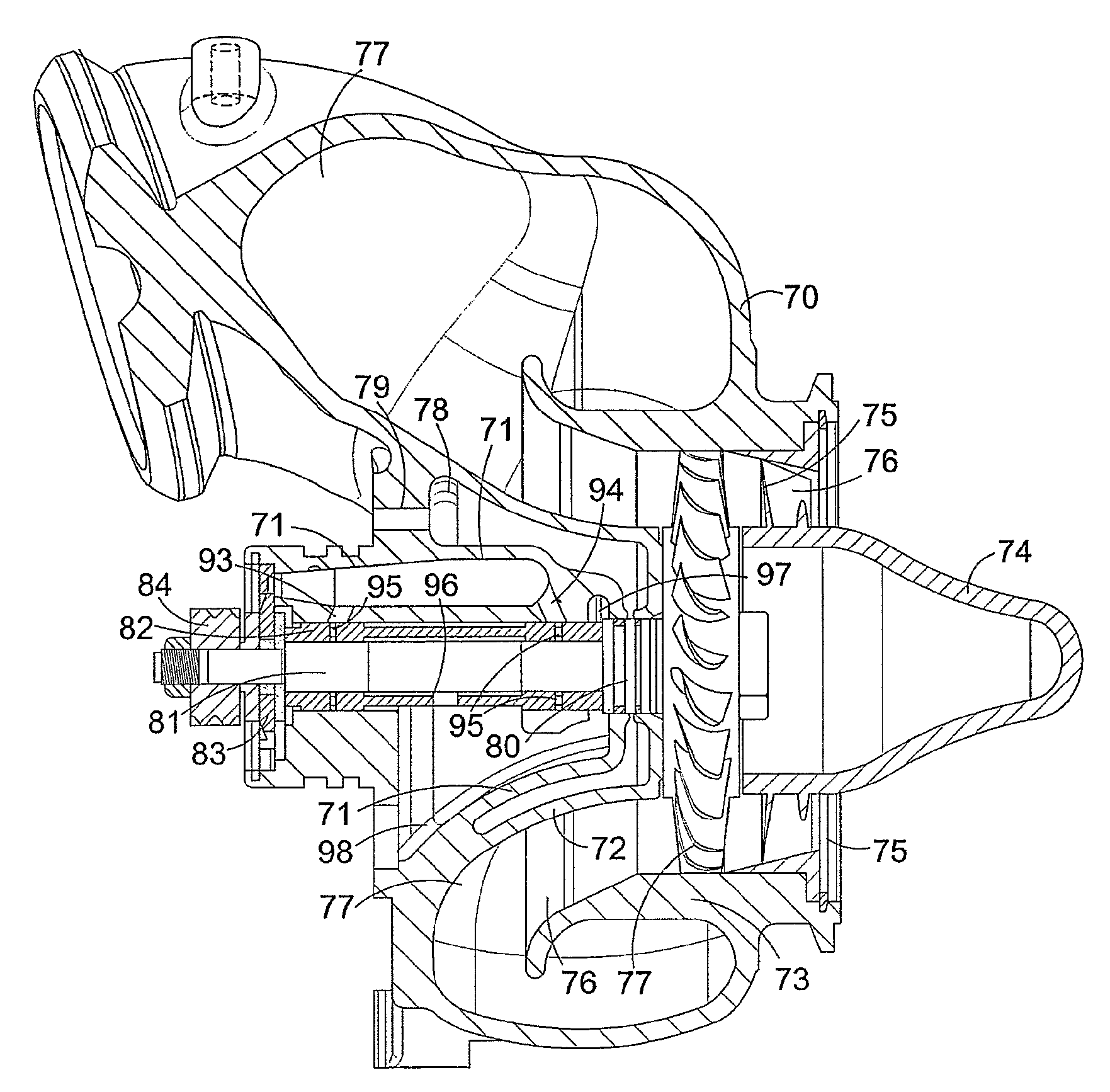
The present invention aims to prevent or minimize the problem of oil leakage from a turbomachine bearing housing into the turbine housing or heatshield. The invention achieves this by raising the pressure in the passage that connects the bearing cavity and the turbine chamber. This reduces the tendency of oil to leak across the first seal, and the pressure within the heat shield cavity is preferably raised above that typically established within the bearing cavity adjacent the first aperture. Additionally, the invention provides a method for reducing oil leakage in a turbomachine by implementing these techniques.

Problems solved by technology

It is well known that providing an effective sealing system to prevent oil leakage from the central bearing housing into the turbine housing is problematic.

Method used


Image

  • Turbomachine
  • Turbomachine
  • Turbomachine

Examples


Embodiment Construction

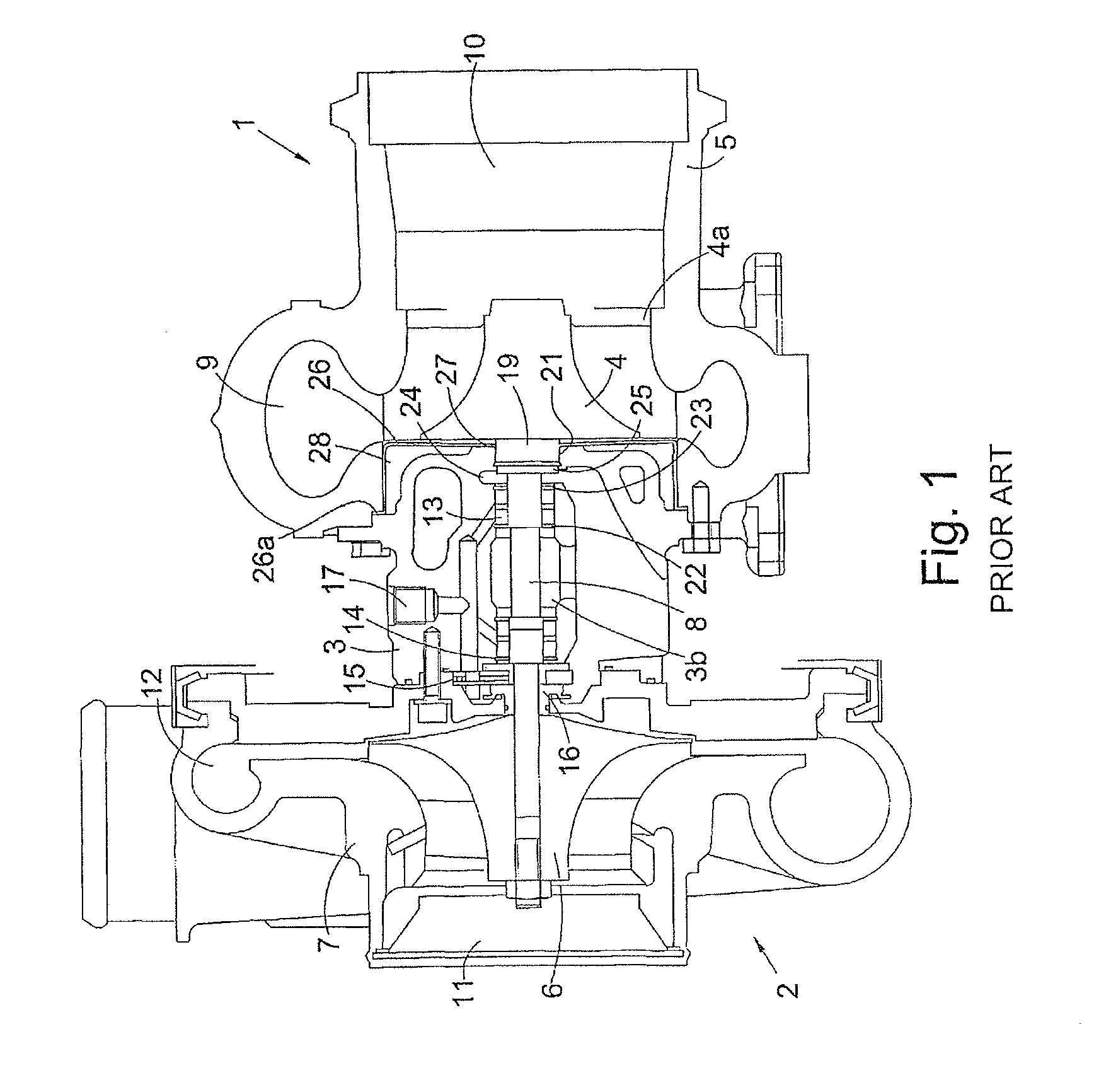
[0044]Referring to FIG. 1, the illustrated turbocharger (as disclosed in U.S. Pat. No. 7,086,842) comprises a turbine 1 joined to a compressor 2 via a central bearing housing 3. The turbine 1 comprises a turbine wheel 4 rotating within a turbine housing 5. Similarly, the compressor 2 comprises a compressor wheel 6 which rotates within a compressor housing 7. The turbine wheel 4 and compressor wheel 6 are mounted on opposite ends of a common turbocharger shaft 8 which extends through the central bearing housing 3.

[0045]The turbine housing 5 has an exhaust gas inlet volute 9 located annually around the turbine wheel 4 and an axial exhaust gas outlet 10. The compressor housing 7 has an axial air intake passage 11 and a compressed air outlet volute 12 arranged annually around the compressor wheel 6.

[0046]In use, the turbine wheel 4 is rotated within a turbine chamber 4a by the passage of exhaust gas from the annular exhaust gas inlet 9 to the exhaust gas outlet 10, which in turn rotates...


PUM

PropertyMeasurementUnit
Pressureaaaaaaaaaa
Diameteraaaaaaaaaa
Circumferenceaaaaaaaaaa

Abstract

A turbomachine comprising a housing defining a bearing cavity and a turbine chamber separated by a first wall, a heat shield disposed between the first wall and the turbine wheel, a heat shield cavity defined between the first wall and the heat shield. The shaft extends through a passage defined in part by a first aperture in the wall and a second aperture in the heat shield. A first seal is provided between the shaft and the first aperture. The housing defines a first gas channel communicating with the heat shield cavity for connection to a pressure source for raising pressure within the heat shield cavity. A second channel is provided between the heat shield cavity and the passage, the second channel opening to the passage on the opposite side of the first seal to the bearing assembly. A second seal is provided between the shaft and the second aperture.

Description

CROSS REFERENCE TO RELATED APPLICATIONS[0001]The present application is a continuation of U.S. patent application Ser. No. 12 / 757,992 filed Apr. 10, 2010, which is a continuation of PCT / GB2008 / 003460 filed Oct. 10, 2008, which claims priority to United Kingdom Patent Application No. 0720478.7 filed Oct. 13, 2007, each of which is incorporated herein by reference.BACKGROUND OF THE INVENTION[0002]The present invention relates to turbomachinery, such as for instance a power turbine or turbocharger for an internal combustion engine. In particular, the present invention relates to the reduction of oil leakage from a turbomachine bearing housing into a turbine housing or a cavity behind a heat shield.[0003]Turbochargers are well known devices for supplying air to the intake of an internal combustion engine at pressures above atmospheric (boost pressures). A conventional turbocharger essentially comprises an exhaust gas driven turbine wheel mounted on a rotatable shaft within a turbine hou...

Claims


Application Information

Patent Timeline
IPC IPC(8): F01D25/08
CPCF02C7/28F16J15/164F16J15/441F05D2240/70F01D25/145F05D2220/40F16C2360/24F05D2250/314F01D25/183F01D11/003F01D25/186F05D2240/40F16J15/006Y10T29/4932
Inventor GEE, DAVIDENRIGHT, CHRISHOLROYD, ROBERT
Owner CUMMINS TURBO TECH
Learn More