EEPROM cell with transfer gate

a transfer gate and eeprom technology, applied in the field of eeprom cells, can solve the problems of unstable control operation of an element, complex control operation, and inability to recycle eeproms, and achieve the effect of reducing instability

Inactive Publication Date: 2014-05-20
ELECTRONICS & TELECOMM RES INST
View PDF14 Cites 6 Cited by
  • Summary
  • Abstract
  • Description
  • Claims
  • Application Information

AI Technical Summary

Benefits of technology

[0010]The present invention has been made in an effort to present an EEPROM cell having advantages of reducing instability by protecting data that is stored at the EEPROM cell by preventing a disturbance phenomenon of data for a standby operation of the EEPROM cell.

Problems solved by technology

When the CMOS element is not used in the EEPROM, an array of the EEPROM and a design rule of a related circuit increase, a control circuit of a chip should be manually designed, and design contents should be constructed with hard intellectual property (IP), and even if a design is changed a little, there is a problem that recycling of the EEPROM is impossible.
However, in a process at 65 nm or lower, when a CMOS element is used and an array of an existing EEPROM cell is applied, a control operation of an element becomes unstable.
However, for stability of a control operation, when an array of the EEPROM cell is newly designed, an outside line is separately added and thus a control operation becomes complicated.
In order to solve a problem in the above process at 65 nm or lower, by forming a tunneling oxide film to a size of 26 Å or lower, a method of reducing a cell area of the EEPROM and simplifying a peripheral control circuit was suggested, but there is a problem that a disturbance phenomenon in which data that has been previously programmed for programming erasing standby time is erased occurs.

Method used


Image

  • EEPROM cell with transfer gate
  • EEPROM cell with transfer gate
  • EEPROM cell with transfer gate

Examples


Embodiment Construction

[0025]In the following detailed description, only certain exemplary embodiments of the present invention have been shown and described, simply by way of illustration. As those skilled in the art would realize, the described embodiments may be modified in various different ways, all without departing from the spirit or scope of the present invention. Accordingly, the drawings and description are to be regarded as illustrative in nature and not restrictive. Like reference numerals designate like elements throughout the specification.

[0026]In addition, in the entire specification and claims, unless explicitly described to the contrary, the word “comprise” and variations such as “comprises” or “comprising” will be understood to imply the inclusion of stated elements but not the exclusion of any other elements.

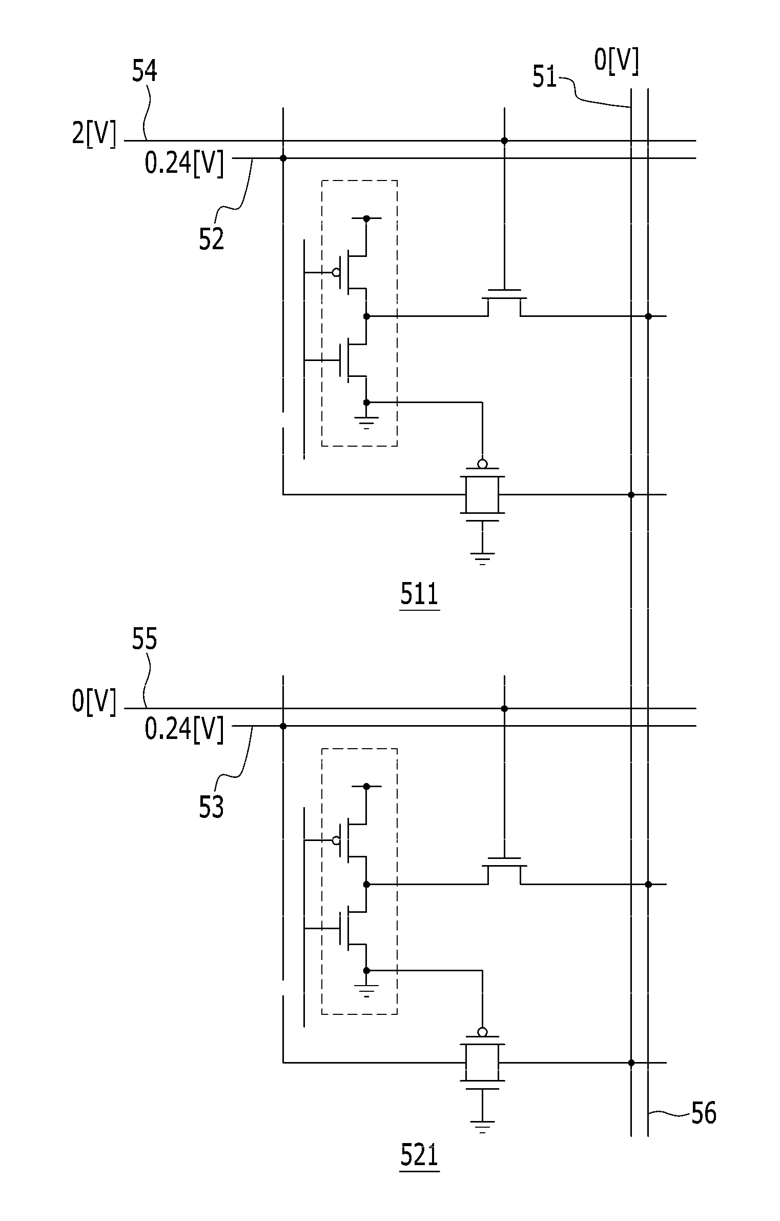
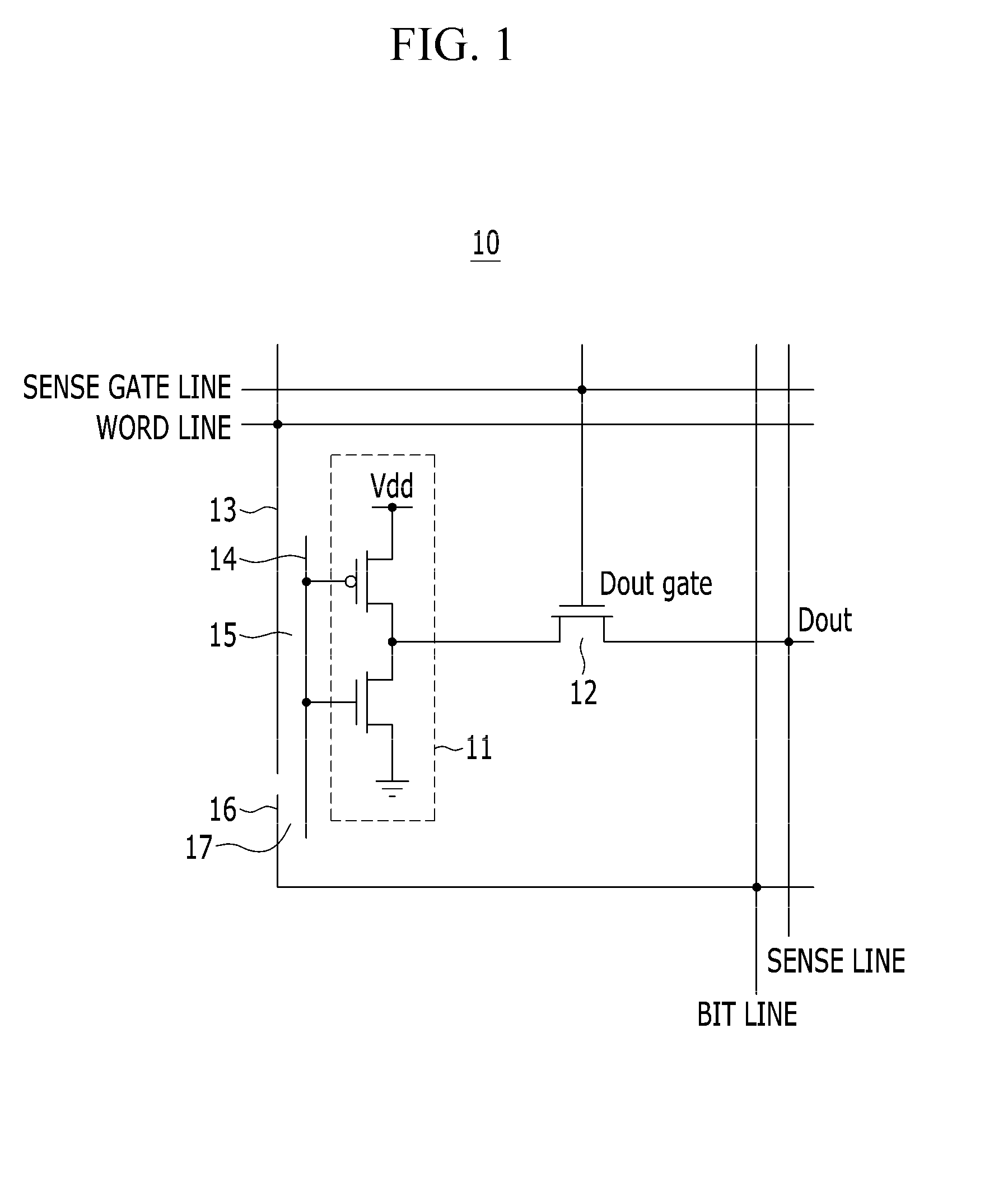
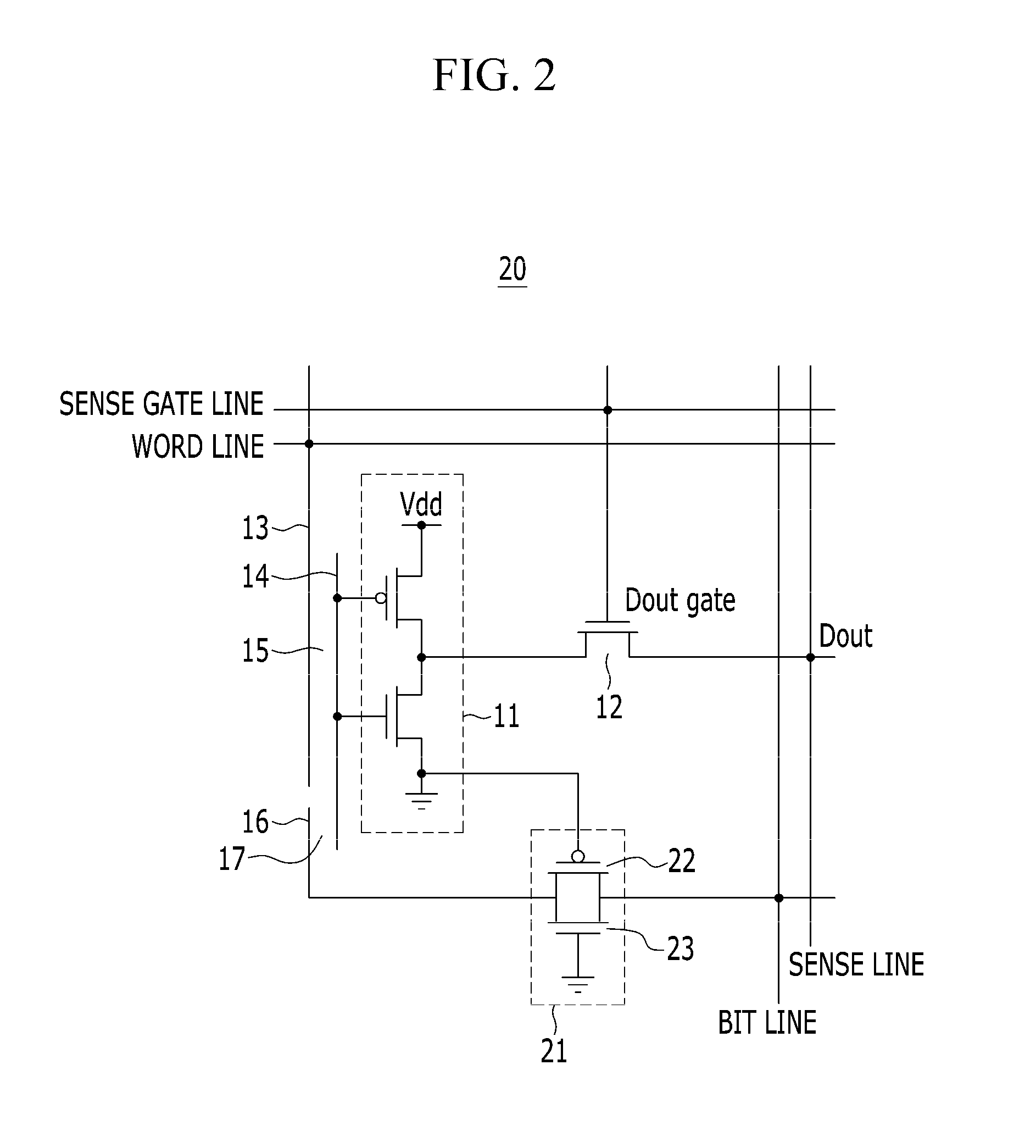
[0027]Hereinafter, an EEPROM cell and programming, erasing, standby, and sense operations of the EEPROM cell according to an exemplary embodiment of the present invention will be d...


PUM


Abstract

An EEPROM cell including a transfer gate that can suppress a data disturbance phenomenon of the EEPROM cell is provided. The EEPROM cell includes: an inverter; a control plate; a tunneling plate; a data output metal oxide semiconductor field effect transistor (MOSFET) that is connected to the inverter; a floating plate that is connected to the inverter; a tunneling capacitor area that is formed between the floating plate and the tunneling plate; and a transfer gate that is connected to the tunneling plate. As the transfer gate is added between a bit line and the tunneling plate of the EEPROM cell, in a standby (or unselected) operation of the EEPROM cell, the tunneling plate is floated.

Description

CROSS-REFERENCE TO RELATED APPLICATION[0001]This application claims priority to and the benefit of Korean Patent Application No. 10-2012-0044066 filed in the Korean Intellectual Property Office on Apr. 26, 2012, the entire contents of which are incorporated herein by reference.BACKGROUND OF THE INVENTION[0002](a) Field of the Invention[0003]The present invention relates to an EEPROM cell. More particularly, the present invention relates to an EEPROM cell into which a transfer gate is inserted to reduce instability of data that is stored at the EEPROM cell during a standby operation thereof.[0004](b) Description of the Related Art[0005]An electrically erasable programmable read-only memory (EEPROM) is a kind of a programmable read-only memory (PROM), and is a ROM that improves a drawback of an erasable programmable read-only memory (EPROM) that can erase contents when radiating ultraviolet rays. The EEPROM erases internal data by applying an electrical signal to a pin of a chip.[0006...

Claims


Application Information

Patent Timeline
Patent Type & Authority Patents(United States)
IPC IPC(8): G11C11/56G11C11/34G11C16/10
CPCG11C16/045G11C16/10G11C11/5628G11C16/0483
Inventor KANG, JIN-YEONG
Owner ELECTRONICS & TELECOMM RES INST
Why Eureka
Try Eureka