Optical fiber

a technology of optical fibers and fibers, applied in the field of optical fibers, can solve the problems of high bend loss of optical fibers, low productivity, and large attenuation, and achieve the effect of improving osnr

Active Publication Date: 2014-05-20
SUMITOMO ELECTRIC IND LTD
View PDF11 Cites 5 Cited by
  • Summary
  • Abstract
  • Description
  • Claims
  • Application Information

AI Technical Summary

Benefits of technology

[0010]Accordingly, it is an object of the present invention to provide an optical fiber that is preferably used for an optical transmission line in an optical communication system and that can improve OSNR.
[0022]The optical fiber according to the present invention is preferably used for an optical transmission line in an optical communication system and can improve OSNR.

Problems solved by technology

Also, these optical fibers are expected to have a high bend loss (more particularly, micro-bend loss).
Hence, it is expected that the productivity may be not high and the attenuation may be large.
In addition, it can be easily expected that the splice loss be increased because the void of these optical fiber is collapsed during fusion splicing with other optical fiber and hence the waveguide structure is changed.

Method used


Image

  • Optical fiber
  • Optical fiber
  • Optical fiber

Examples


examples

[0073]Next, Examples 1 to 10 of optical fibers according to the present invention are described. Any of the optical fibers of Examples 1 to 10 is made of silica-based glass and was manufactured by a known method.

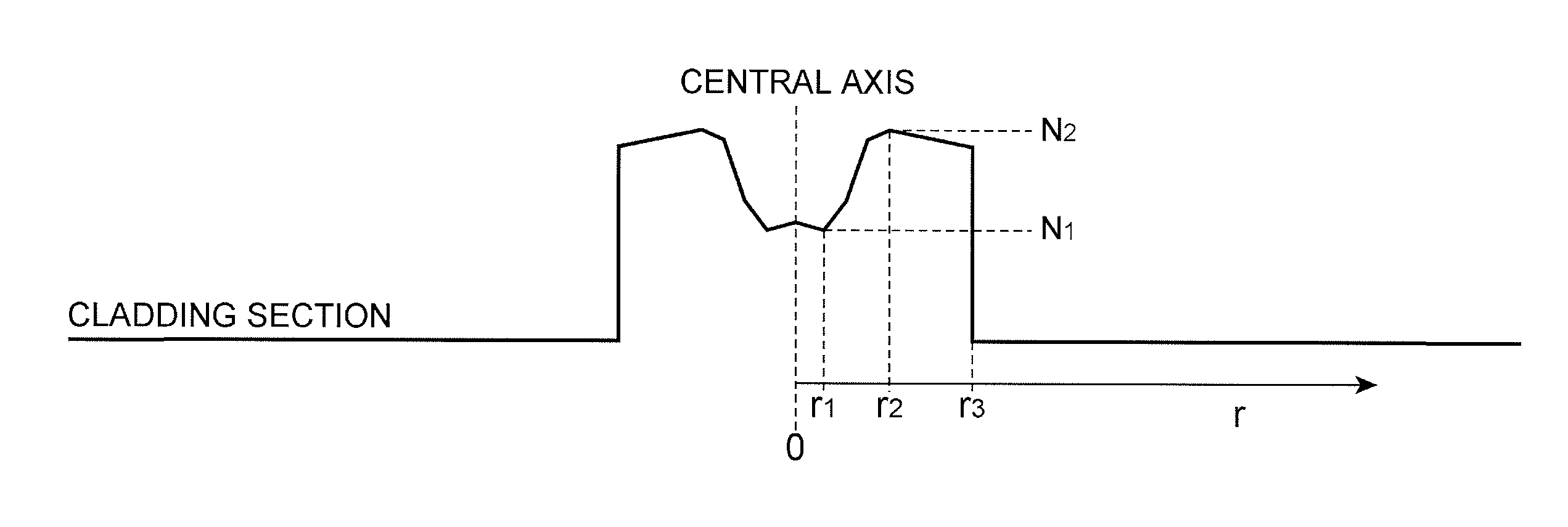
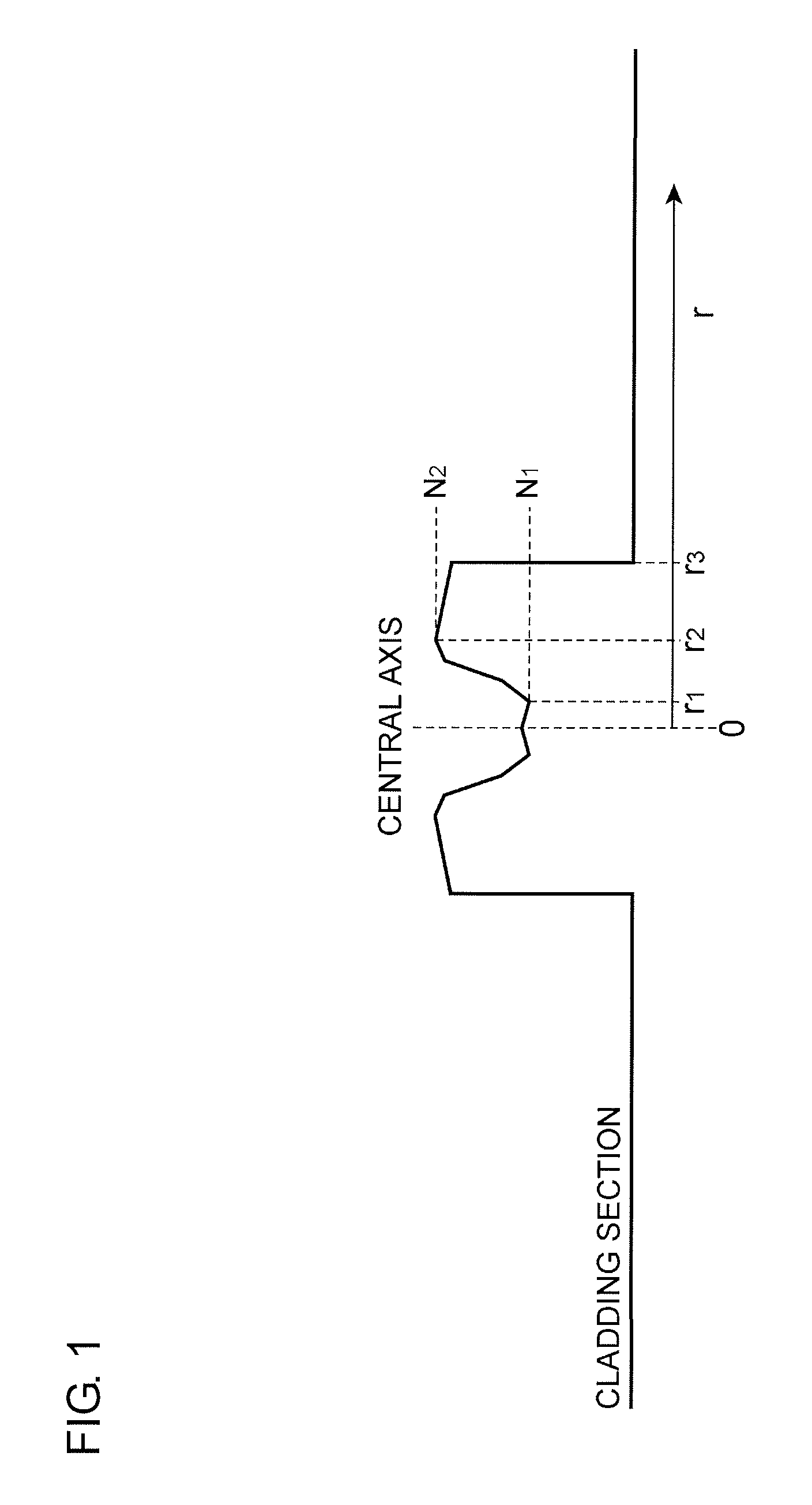
[0074]FIG. 9 is an illustration schematically showing a refractive index profile of each of the optical fibers according to Examples 1 to 5. In each of the optical fibers according to Examples 1 to 5, a core section included a first core portion with a low refractive index and a second core portion with a high refractive index. Chlorine, fluorine, and low-concentration GeO2 were doped to the first core portion. Chlorine, fluorine, and high-concentration GeO2 were doped to the second core portion. The cladding section also had a refractive index profile. Chlorine and fluorine were doped to a first cladding portion with a low refractive index, and chlorine was doped to a second cladding portion with a high refractive index.

[0075]FIG. 10 is an illustration schematically showing...


PUM


Abstract

An optical fiber includes a core section and a cladding section. A k value expressed by k=4Aeff / (πMFD2) is 1.08 or larger, Aeff being an effective area and MFD being a mode field diameter, at a wavelength of 1550 nm, a chromatic dispersion is in a range from +19.0 ps / nm / km to +21.9 ps / nm / km, and MFD is in a range from 10.3 μm to 13.0 μm. The inequality, r1<r2<r3, is established, R=r3 / r2 is larger than 1.0 and equal to or smaller than 5.4, and a relative refractive index difference Δ12 of the maximum value N2 with respect to the minimum value N1 is 0.05% or higher, r1 and r2 being radial positions respectively with minimum and maximum value N1 and N2 of a refractive index in the core section and r3 being a radius of the core section.

Description

[0001]This application claims the benefit of U.S. Provisional Application No. 61 / 538,428, filed Sep. 23, 2011, which is incorporated by reference herein in its entirety.BACKGROUND OF THE INVENTION[0002]1. Field of the Invention[0003]The present invention relates to an optical fiber.[0004]2. Description of the Related Art[0005]In an optical communication system, it is desirable to improve an optical signal-to-noise ratio (OSNR). The improvement in OSNR is particularly important for a communication using a digital coherent detection. By improving OSNR, the capacity of transmission signals can be increased, the transmission distance of the optical communication system can be increased, and the interval between repeaters can be increased. Thus, the performance of the optical communication system can be improved.[0006]To improve OSNR, it is important to reduce the non-linearity of an optical fiber used as an optical transmission line and to reduce the attenuation in the optical transmiss...

Claims


Application Information

Patent Timeline
Patent Type & Authority Patents(United States)
IPC IPC(8): G02B6/028G02B6/02
CPCG02B6/02004G02B6/0228G02B6/03633G02B6/0281G02B6/0365G02B6/02266G02B6/02019G02B6/03627G02B6/028G02B6/03611G02B6/02219G02B6/02214
Inventor HIRANO, MASAAKIHARUNA, TETSUYATAMURA, YOSHIAKIYAMAMOTO, YOSHINORI
Owner SUMITOMO ELECTRIC IND LTD
Why Eureka
Try Eureka