Blade server apparatus

a server and blade technology, applied in the field of blade server apparatus, can solve problems such as problems, deterioration of signal transmission quality, and deterioration of performance, and achieve the effects of reducing wiring length, reducing cost, and improving signal transmission quality

Active Publication Date: 2014-06-03
HITACHI LTD
View PDF11 Cites 49 Cited by
  • Summary
  • Abstract
  • Description
  • Claims
  • Application Information

AI Technical Summary

Benefits of technology

[0016]In accordance with an aspect of the present invention, even when a restriction is imposed on how to define the connection destinations of processors to be SMP coupled and to define the processor ID, a different ID can be informed to the SMP virtual connecting unit independently of the restricted processor ID and thus the connection destination of the SMP coupling can be optimized regardless of the restriction of the ID definition. Since this can reduce the wiring length of an 8-connection type SMP coupling device, thus improving a signal transmission quality.
[0017]When a substrate of the 8-connection type SMP coupling device is made of an ultra-low-loss material of characteristics twice as good as a usual material, the server module and a 4-connection type SMP coupling device can be made of an inexpensive material with a reduced cost.
[0018]Since the wiring length of the 8-connection type SMP coupling device is twice that of the 4-connection type SMP coupling device, employment of the ultra-low-loss material having the twice characteristics causes electrical loss characteristics of the 4- and 8-connection type SMP coupling devices to become nearly equal. As a result, as long as sufficient evaluation is made with the 4-connection type SMP coupling arrangement, even when the test evaluation of the 8-connection type SMP coupling arrangement becomes late, a risk of a problem later picked up can be remarkably reduced and its development cost can be reduced in a broad sense.

Problems solved by technology

For example, when a server apparatus is designed to simultaneously satisfy a restriction based on a processor architecture and a restriction based on apparatus specifications, the wiring length of the SMP coupling apparatus disclosed in JP-A-2010-079467 becomes much longer, which may, in some cases, deteriorate a signal transmission quality.
According to the processor architecture, however, a change in a relationship between the processor ID and the wiring line causes the function not to be lost, which results in that packets are concentrated on a specific wiring line, thus deteriorating the performance.
When the same restrictions are applied to SMP coupling of 8 processors, a problem takes place. FIG. 10 shows an example of arrangement of a server apparatus having 8 of the processors 400 SMP coupled, and FIG. 11 is its mounting example.
When design is made so as to fit these restrictions simultaneously in this way, there may in some cases, occur such a situation that the wiring length of the 8-connection type SMP coupling device becomes 3 times longer than that of the 4-connection type SMP coupling device and a signal transmission quality for the SMP coupling is remarkably deteriorated.
In this connection, even when the substrate is made of an expensive ultra-low-loss material, the expensive substrate can only provide characteristics about 2 times as good as a general-purpose substrate material as its limit.
Thus, it is insufficient to only employ such an ultra-low-loss material for the substrate of the 8-connection type SMP coupling device 50 and it becomes necessary to employ the ultra-low-loss material even for the substrate of the server module 10.
In this case, since the cost of the server module is increased, the employment of the ultra-low-cost material becomes costly for a lower-level arrangement such as a case of no SMP coupling or a case of 4-connection type SMP coupling.
Problems based on the evaluation are picked up most frequently upon evaluation of the smallest-operational margin arrangement For this reason, there is a risk that problem pickup becomes late and thus this leads to a cost increase in a broad sense.

Method used


Image

  • Blade server apparatus
  • Blade server apparatus
  • Blade server apparatus

Examples


Embodiment Construction

[0031]An embodiment of the present invention will be explained with use of the attached drawings.

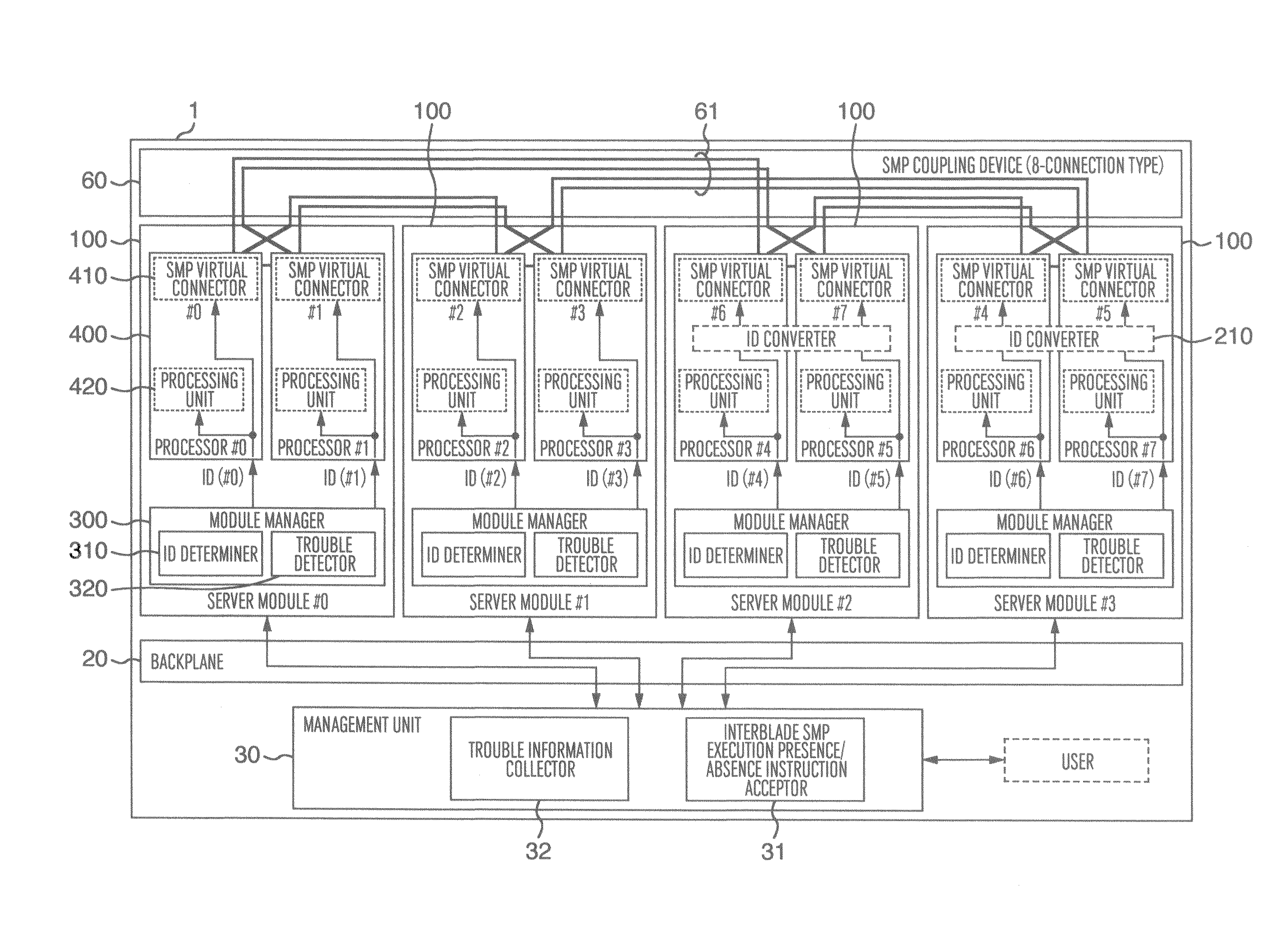
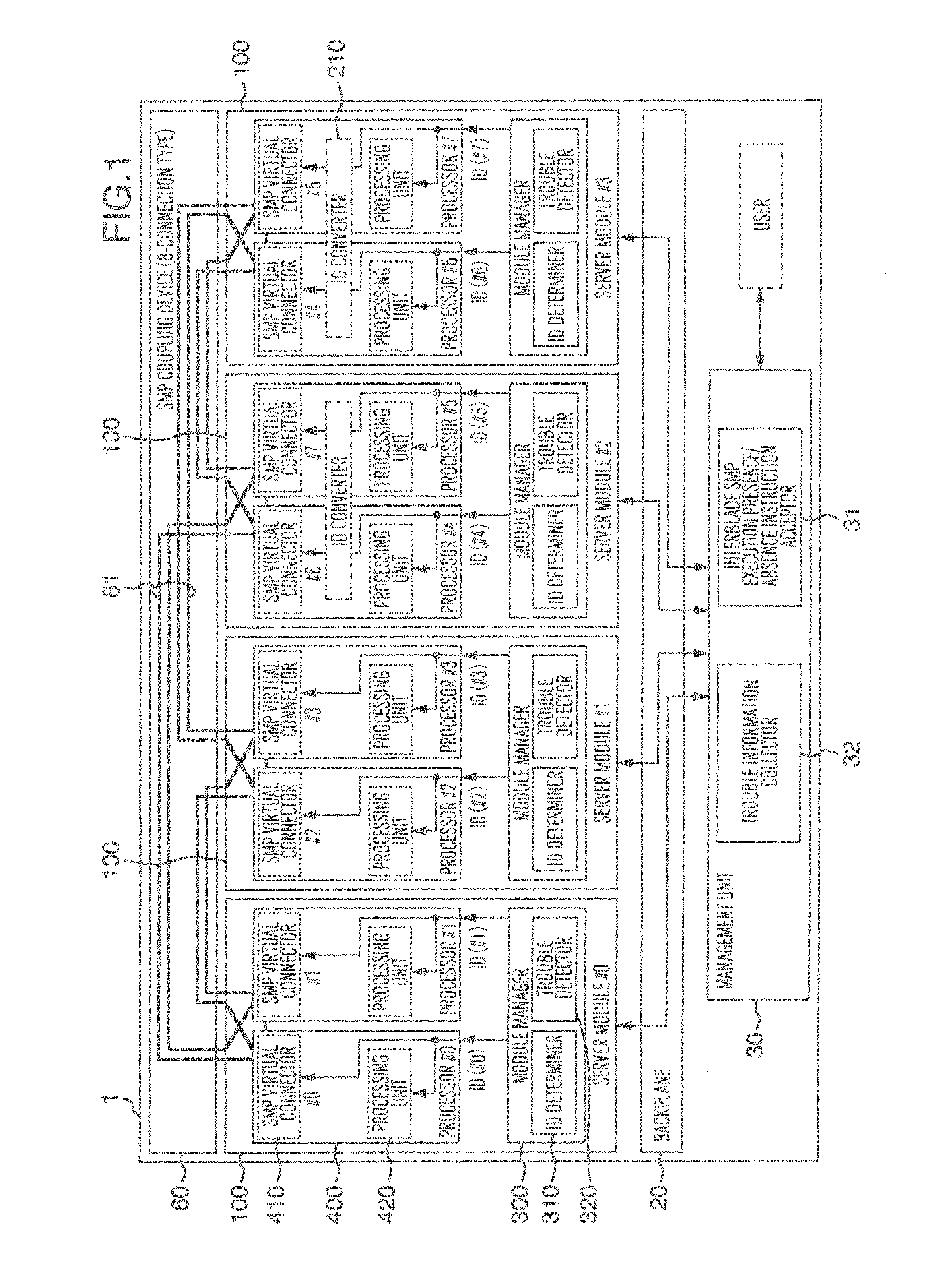
[0032]In the present embodiment, explanation will be made in connection with an example wherein a server apparatus employs a technique for shortening the wiring length of an SMP coupling device of an 8-connection type arrangement.

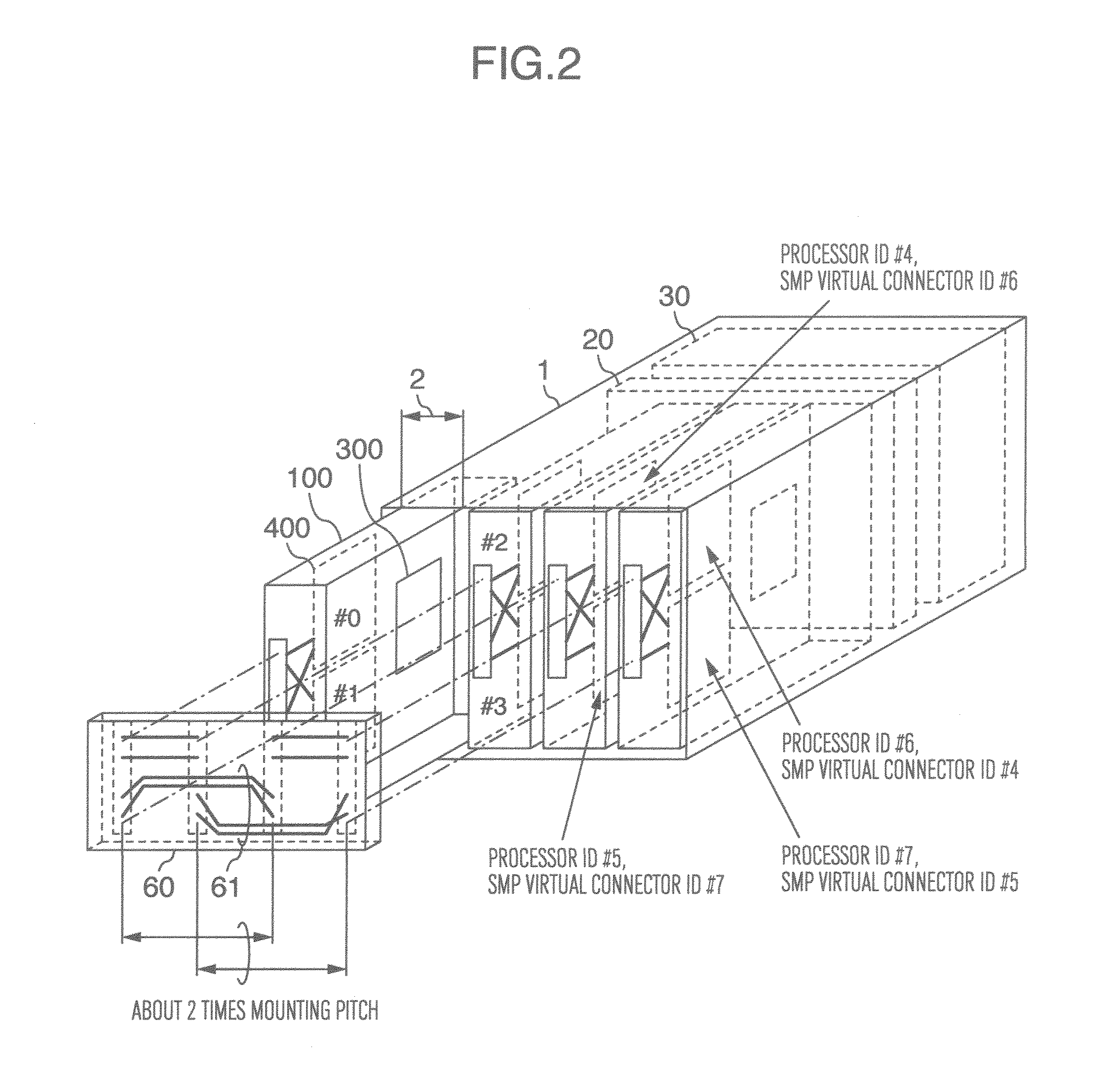
[0033]FIG. 1 is an example of arrangement of an 8-connection type SMP coupling server apparatus in accordance with an embodiment 1, and FIG. 2 is a mounting example thereof Constituent elements denoted by the same reference numeral have the same function. The prior art of FIG. 10 is different from the prior art of FIG. 11 in that an ID converter 210 is provided within a server module 100 to be mounted, and the ID converter informs the SMP virtual connecting unit 410 of a processor ID after converted, the wiring length of a longest wiring line 61 of an SMP coupling device 60 is equal to nearly twice a mounting pitch 2 of server modules 100 in FIG. 2 and thus is m...


PUM


Abstract

A blade server apparatus including a plurality of server modules, a backplane for mounting the plurality of server modules thereon, and an SMP coupling device having wiring lines to SMP couple the plurality of server modules. Each of the server modules has one or more processors controlled by firmware and a module manager for managing its own server module, the module manager has an ID determiner for informing each processor of a processor ID, each processor has a processing unit and an SMP virtual connecting unit for instructing ones of wiring lines of the SMP coupling device through which a packet received from the processing unit is to be transmitted, and an ID converter for converting the processor ID and informing it to the SMP virtual connecting unit is provided within the firmware.

Description

INCORPORATION BY REFERENCE[0001]The present application claims priority from Japanese application JP2010-193057 filed on Aug. 31, 2010, the content of which is hereby incorporated by reference into this application.BACKGROUND OF THE INVENTION[0002]The present invention relates to a blade server apparatus which can form a high-performance server by tightly coupling a plurality of blade server modules, and more particularly, to a blade SMP server apparatus which employs a symmetric multi-processing (SMP) system.[0003]As a known technique of the present invention, a technique for SMP coupling a plurality of blade server modules via a backplane is disclosed in JP-A-2010-009628 (the counterpart US Publication of which is US2011 / 0016201). A technique for obtaining physical SMP coupling according to a logical SMP arrangement by providing a removable SMP coupling apparatus which mounts blade server modules in place of wiring lines on a backplane is disclosed in JP-A-2010-079467.[0004]In ord...

Claims


Application Information

Patent Timeline
Patent Type & Authority Patents(United States)
IPC IPC(8): G06F3/00
CPCG06F15/7803
Inventor IKEYA, AKIOAOYAGI, TAKASHIKASHIWAGI, KENJISEZAKI, NAOHIRONAKAJIMA, KAZUNORI
Owner HITACHI LTD
Why Eureka
Try Eureka