System and method for providing a reserve supply of gas in a pressurized container

a technology of gas reserve supply and pressurized container, which is applied in the direction of liquid flow controller, liquid transfer device, packaging, etc., can solve the problems of general ineffectiveness of activated carbon, and achieve the effects of economic, environmental and economic safety

Inactive Publication Date: 2014-06-10
LIM WALTER K
View PDF26 Cites 3 Cited by
  • Summary
  • Abstract
  • Description
  • Claims
  • Application Information

AI Technical Summary

Benefits of technology

[0026]The present invention provides a system and method to replenish and maintain a desired pressure in pressurized containers such as aerosol dispensers, pressurized beverage containers, or dispensers of the gas, such as, e.g., carbon dioxide fire extinguishers. In particular, the present invention provides an economical, efficient, and environmentally safe system and method for providing a reserve supply of gas in a pressurized container. More specifically, the present invention provides a system and method for providing a reserve supply of gas to restore and maintain propellant pressure as product is depleted from a container, wherein the gas is adsorbed or absorbed on a gas adsorbent or absorbent material and means is provided to promote release of the stored gas from the sorbent material.
[0032]While the foregoing systems perform better than prior art systems that do not store reserve propellant in a sorbent, applicant has found that the quantity of gas desorbed (such as, e.g., carbon dioxide, nitrous oxide, or oxygen, and the like) is significantly increased when a polar organic fluid such as ethyl alcohol, acetone, water, or the like, or combinations thereof, and / or a surfactant, is added to the sorbent material (e.g., activated carbon, zeolite, or molecular sieve material). If zeolite is used as the sorbent material, water alone is effective to promote release of the sorbed gas. The polar fluid preferably is added in an amount sufficient just to wet the sorbent material. Alternatively, when the sorbent material is placed directly in contact with the product, a separate wetting agent may not be necessary or desired if the product itself contains a polar solvent, e.g., water or alcohol.
[0033]Controlling the release of gas is dependent upon the ratio of the quantity of the polar organic fluid to the quantity of sorbent material, and / or by varying the amount of sorbent material relative to the pressure in the container. Further control can be achieved by diluting the polar fluid with water or a non-polar fluid prior to adding the polar fluid to the container. Moreover, if the polar fluid is in gel form, it can take longer for the active component to enter the sorbent material, thus controlling the rate of desorption of the gas.
[0034]In a preferred embodiment the polar fluid comprises alcohol diluted with water. The extent of dilution can be selected dependent upon the desired results, but in a preferred embodiment the dilution is 25% alcohol, i.e., one part by weight of alcohol to three parts by weight of water. Of course, the polar fluid could comprise 100% water, or any percentage of polar fluid, e.g., alcohol, or combinations thereof. Release of sorbed gas is more easily controlled when the polar fluid comprises water, but a quicker release of sorbed gas can be achieved when the polar fluid comprises alcohol or a similar material. When the sorbent material comprises activated carbon and is wetted with a polar fluid (e.g., a 25% solution of alcohol and water) at a ratio of 13% polar fluid to sorbent, carbon dioxide release is increased by about 50% relative to conventional systems that do not wet the sorbent material with a polar fluid. Thus, in the system of the invention 90% or more of the sorbed gas is released from the sorbent. Zeolite is particularly effective as a sorbent material, especially in barrier packs, enabling a lesser amount of sorbent to be used. For example, good results are obtained when ½ ounce of zeolite is used as the sorbent in a barrier pack system at 60 psi.
[0042]The use of activated carbon to adsorb additional gas in an aerosol container can increase the available gas to a level that results in the pressure remaining more uniform until the product is depleted. This, in turn, maintains a more consistent, uniform and acceptable spray pattern from beginning to end because the pressure at the end is very close to the starting pressure. In some applications, release of make-up gas pressure into the product may be desirable in order to better aerosolize the product throughout the life cycle of the container, or to achieve better foaming, etc.
[0044]With the barrier pack piston or bag-in-a-can system, CO2 gas can be charged into the product to a pressure lower than the pressure below the piston or outside the bag, dissolving the CO2 in the product. This can be especially beneficial for some products, such as hair spray, since the dissolved CO2 will aid in the break-up of the product when it is sprayed. It would also help reduce clogging of the spray nozzle, for example, by resinous materials. That is, the extra propellant provided by the system of the invention provides benefits in addition to reserve propellant for discharging the product. With the gas storage system of the present invention, the pressure source chamber could be pressurized to 80-100 psig and the product chamber could be pressurized to 50 psig, for example, which pressures would be maintained until the product has been emptied, thereby maintaining a uniform spray pattern throughout the life of the container.

Problems solved by technology

Other materials, such as natural or synthetic zeolite, starch-based polymers, alumina—preferably activated alumina, silica gel, and sodium bicarbonate, or mixtures thereof, may be used to adsorb and store a quantity of a desired gas, although they generally are not as effective as activated carbon.

Method used


Image

  • System and method for providing a reserve supply of gas in a pressurized container
  • System and method for providing a reserve supply of gas in a pressurized container
  • System and method for providing a reserve supply of gas in a pressurized container

Examples


Embodiment Construction

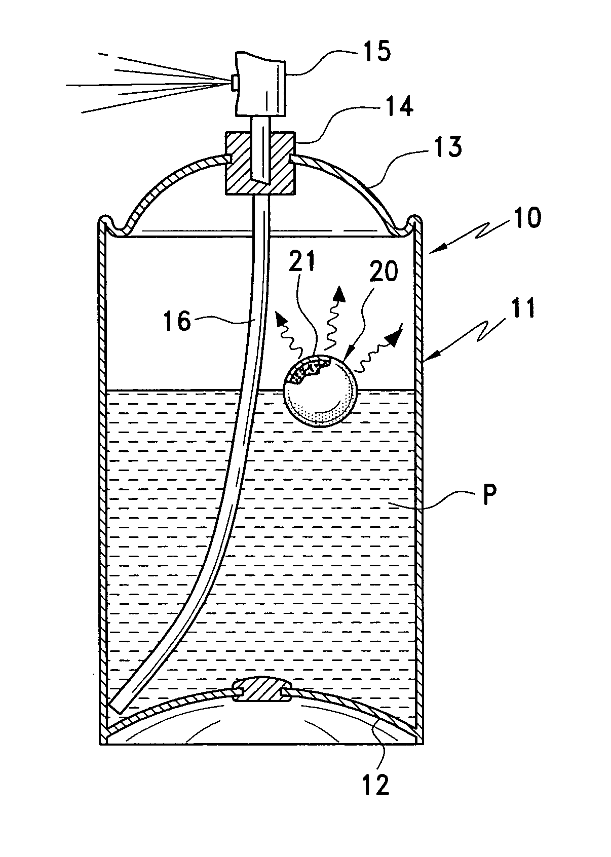
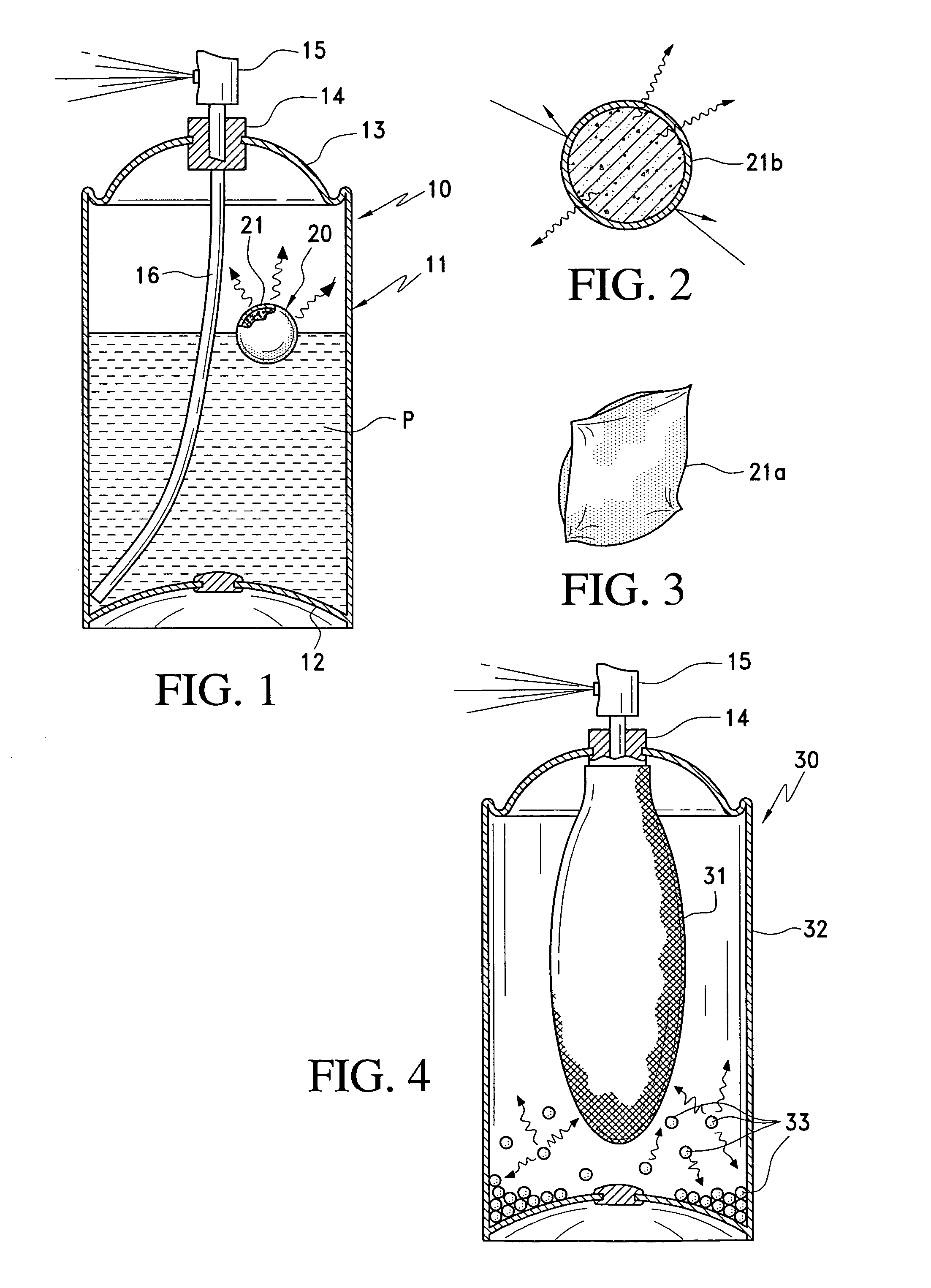
[0063]A first form of aerosol dispenser is indicated generally at 10 in FIG. 1. The dispenser includes a container 11 made of metal or other suitable material, having a bottom 12 and a top 13. A discharge nozzle assembly 14 is mounted on the top and includes a nozzle 15 that may be manually depressed to open and permit product P to be dispensed from the container through the nozzle. A dip tube 16 extends from the bottom of the container to the discharge nozzle assembly. As seen in this figure, the level of product in the container does not occupy the entire volume of the container, and the space above the product level is filled with a pressurized propellant gas to exert pressure on the product and force it through the dip tube and nozzle when the nozzle is depressed. The foregoing structure and operation are conventional, and further detailed description of these basic components and their operation is not believed necessary.

[0064]In accordance with the invention, a body 20 of a ga...


PUM


Abstract

A gas storage and delivery system for restoring pressure as it is depleted from a pressurized container, includes a container holding a product under pressure to be dispensed from the container, a quantity of gaseous material under pressure, occupying a space in the container and applying to the product a predetermined pressure of from about 30 to about 180 psig, and a quantity of gas-adsorbing material, storing under pressure a quantity of the gaseous material and releasing it into the container in response to a decrease in pressure in the container, thereby restoring and maintaining a predetermined pressure in the container as product is depleted from the container, wherein the gas-adsorbing material is wetted with a release-promoting agent to promote release of the sorbed gas from the gas-adsorbent material. A process of filling the container is also disclosed.

Description

[0001]This application claims the benefit of U.S. Provisional Patent Application Ser. No. 60 / 650,338, filed Feb. 4, 2005, and is a continuation-in-part of U.S. application Ser. No. 10 / 866,451, filed Jun. 12, 2004 now U.S. Pat. No. 7,185,786.BACKGROUND OF THE INVENTION[0002]1. Field of the Invention[0003]This invention relates generally to pressurized dispensing containers, and more particularly, to a system and method for providing a reserve supply of gas in a pressurized container, and especially to a system and method for storing gases adsorbed or absorbed on a sorbent material such as, e.g., activated carbon, zeolite, or molecular sieves, in pressurized containers, and subsequently releasing the sorbed material in response to a decrease in pressure below a predetermined level in the container. In one aspect, the reserve supply of gas is used to restore and maintain propellant pressure as the dispensed product and / or propellant are depleted from a pressurized dispensing container,...

Claims


Application Information

Patent Timeline
Patent Type & Authority Patents(United States)
IPC IPC(8): B67D7/00B67D99/00
CPCB65D83/643B65D83/663B65D83/625
Inventor LIM, WALTER K.KRAUSE, ARTHUR A.
Owner LIM WALTER K
Why Eureka
Try Eureka