
Apparatus for estimating exhaust gas recirculation quantity

a technology for which is applied in the direction of electrical control, process and machine control, instruments, etc., can solve the problems of exceeding the range of estimation errors, and the accuracy of estimating the quantity of recirculation exhaust gas does not meet the requirements of fuel economy improvement, so as to accurately estimate the quantity of recirculation exhaust gas flowing

Active Publication Date: 2014-06-10
DENSO CORP
View PDF8 Cites 2 Cited by
  • Summary
  • Abstract
  • Description
  • Claims
  • Application Information

AI Technical Summary

Benefits of technology

The apparatus enables precise computation of recirculated exhaust gas quantity, reducing estimation errors and enhancing fuel economy by accurately accounting for intake air and exhaust gas dynamics, even during transitional engine conditions.

Problems solved by technology

However, in the above EGR system, an estimating accuracy of the quantity of the recirculated exhaust gas does no satisfy a required accuracy to improve a fuel economy.
Especially, when the engine is in a transitional running condition, an estimation error exceeds an allowable error range.

Method used


Image

  • Apparatus for estimating exhaust gas recirculation quantity
  • Apparatus for estimating exhaust gas recirculation quantity
  • Apparatus for estimating exhaust gas recirculation quantity

Examples


Embodiment Construction

[0019]An embodiment of the present invention, which is applied to an internal combustion engine equipped with a turbocharger, will be described hereinafter.

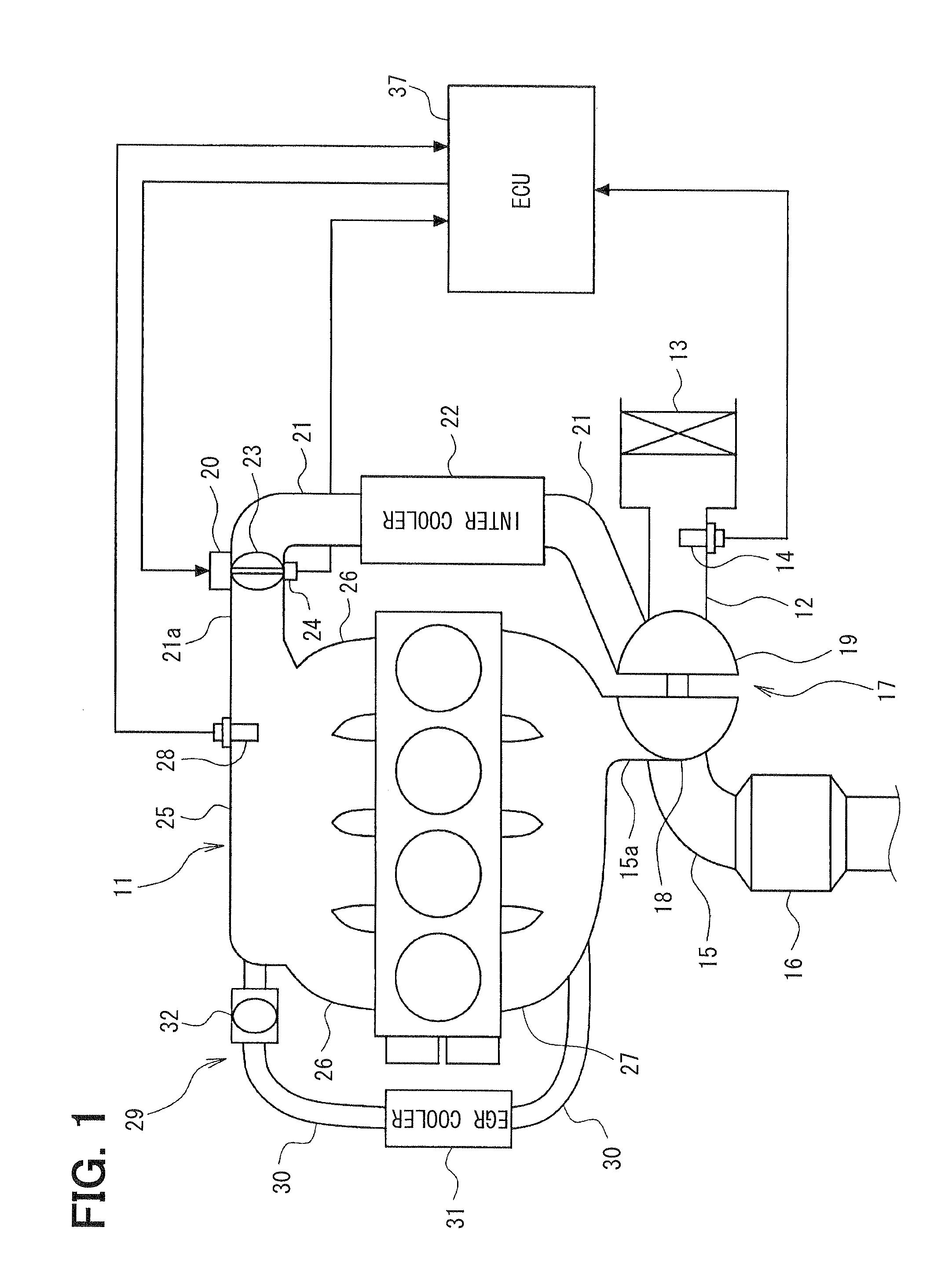
[0020]Referring to FIG. 1, an engine control system will be schematically explained. An air cleaner 13 is arranged upstream of an intake pipe 12 (intake passage) of an internal combustion engine 11. An airflow meter 14 detecting an intake air flow rate is provided downstream of the air cleaner 13. An exhaust pipe 15 (exhaust passage) of the engine 11 is provided with a three-way catalyst 16 which reduces CO, HC, NOx, and the like contained in exhaust gas.

[0021]The engine 11 is provided with the turbocharger 17. The turbocharger 17 includes an exhaust gas turbine 18 arranged upstream of the catalyst 16 in the exhaust pipe 15 and a compressor 19 arranged downstream of the airflow meter 14 in the intake pipe 12. This turbocharger 17 has well known configuration which supercharges the intake air into the combustion chamber.

[0022]An i...


PUM


Abstract

An apparatus estimates a quantity of recirculated exhaust gas. The apparatus includes a first unit computing a total quantity of gas, a second unit computing a quantity of exhaust gas passing through an EGR vale by means of an EGR valve model, a third unit computing a temporal quantity of the exhaust gas by means of an EGR diffusion model which simulates a behavior of the exhaust gas, a fourth unit obtaining an intake air quantity by subtracting the temporal exhaust gas quantity from the total gas quantity, a fifth unit correcting the computed intake air quantity by means of intake air quantity measured by the airflow meter, a sixth unit computing an intake air pressure based on the corrected quantity of the intake air, and a seventh unit computing a quantity of the recirculated exhaust gas based on at least the intake air pressure.

Description

CROSS-REFERENCE TO RELATED APPLICATION[0001]This application is based on Japanese Patent Application No. 2010-239129 filed on Oct. 25, 2010, the disclosure of which is incorporated herein by reference.FIELD OF THE INVENTION[0002]The present invention relates to an apparatus for estimating exhaust gas recirculation quantity which flows into a cylinder of an internal combustion engine.BACKGROUND OF THE INVENTION[0003]JP-2008-101626A shows an exhaust gas recirculation (EGR) system in which quantity of recirculation gas is controlled by an exhaust gas recirculation valve (EGR valve). In this EGR system, the quantity of exhaust gas passing through the EGR valve is computed by means of an EGR valve model which simulates a behavior of the recirculated exhaust gas passing through the EGR valve. When the engine is stably running, it is deemed that the quantity of the exhaust gas passing through the EGR valve is equal to the quantity of the exhaust gas flowing into a cylinder. When the engine...

Claims


Application Information

Patent Timeline
Patent Type & Authority Patents(United States)
IPC IPC(8): F02M25/07F02B47/08F02D41/00
CPCF02D21/08F02B47/08F02D2200/0406F02D2200/0402F02D41/0072F02D41/18Y02T10/47F02M25/0786F02M26/64Y02T10/40
Inventor TAKEZOE, HIROYUKI
Owner DENSO CORP
Learn More