Abnormality detection system, abnormality detection method, recording medium, and substrate processing apparatus
a technology of abnormal discharge and detection method, applied in the direction of instruments, semiconductor/solid-state device testing/measurement, nuclear elements, etc., can solve the problems of abnormal discharge of plasma and -arching, and achieve the effect of reducing data processing costs, large-capacity data, and high precision
- Summary
- Abstract
- Description
- Claims
- Application Information
AI Technical Summary
Benefits of technology
Problems solved by technology
Method used
Image
Examples
modified example 1
[0155]The configurations of trigger generation time counter 54 and data logger boards 55 and 56 are not limited to the above exemplary embodiments, and the clock control of trigger generation time counter 54 and data logger boards 55 and 56 may be performed by one external reference synchronized clock.
modified example 2
[0156]In the exemplary embodiment, the plurality of trigger signals are integrated to one representative trigger signal in OR circuit 53 (the method for processing the second trigger signal), but as a method for generating the representative trigger signal, a method to be described below may also be used.
[0157]That is, a buffer port and a time counter instead of trigger generation time counter 54 are installed in PC 50, such that the external reference synchronized clock gives the time information to the time counter. According to the above method for processing the first trigger signal, OR circuit 53 successively outputs the trigger signals received from trigger 52 to the buffer port according to the time series. A counter value outputted from the time counter is inputted to the buffer port. Accordingly, the counter value is given to the trigger signal.
[0158]The buffer port integrates the plurality of trigger signals within a predetermined period to one representative trigger signa...
modified example 3
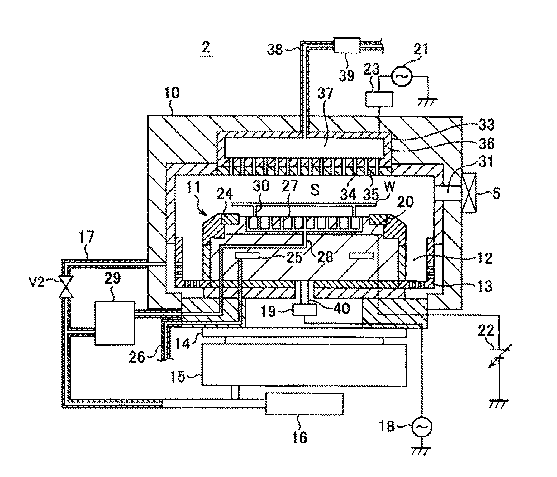
[0160]As another generation method of the representative trigger signal in OR circuit 53, the first received trigger signal as the representative trigger signal is outputted to PC 50 and then, until the time corresponding to the integrated period elapses, a method in which the received trigger signal is not outputted to PC 50 may be used. Even in the method, the trigger generation time determined by trigger generation time counter 54 may be set as a time close to the time when the abnormality actually occurs in plasma processing apparatus 2.
PUM
| Property | Measurement | Unit |
|---|---|---|
| frequency | aaaaa | aaaaa |
| frequency | aaaaa | aaaaa |
| diameter | aaaaa | aaaaa |
Abstract
Description
Claims
Application Information
 - R&D
- Intellectual Property
- Life Sciences
- Materials
- Tech Scout
- Unparalleled Data Quality
- Higher Quality Content
- 60% Fewer Hallucinations
Browse by: Latest US Patents, China's latest patents, Technical Efficacy Thesaurus, Application Domain, Technology Topic, Popular Technical Reports.
© 2025 PatSnap. All rights reserved.Legal|Privacy policy|Modern Slavery Act Transparency Statement|Sitemap|About US| Contact US: help@patsnap.com


