Method and device to determine distortion correction data

a distortion correction and data technology, applied in the direction of measurement devices, instruments, character and pattern recognition, etc., can solve the problems of affecting the accuracy of the calculation, the disadvantage of the imaging properties of the magnetic field gradient coil, and the problem of imaging errors (typically called “distortions”) in the imaging volume, so as to achieve the effect of longer calculation time and consequently more accurate calculation

Inactive Publication Date: 2014-06-17
SIEMENS HEALTHCARE GMBH
View PDF9 Cites 4 Cited by
  • Summary
  • Abstract
  • Description
  • Claims
  • Application Information

AI Technical Summary

Benefits of technology

[0015]An object of the present invention is to provide a method and a device to determine distortion correction data, which allow a faster and more precise determination of distortion correction data for the gradient coil without complicated additional measurement means.
[0022]In the method according to the invention, improved spherical function coefficients are thus determined in a relatively simple manner via a magnetic resonance measurement with a phantom that is typically present at the user in any case, which also takes into account the interference terms caused by the production tolerances. The spherical function coefficients theoretically calculated only on the basis of the design can thereby be used as a basis for the determination of the spherical function coefficients. This has the advantage that the determination of the distortion correction data on the basis of the spherical function coefficients and also the additional method to implement the distortion correction according to the invention can largely ensue in the customary manner, wherein only the additional measurement with the phantom and the fit procedure must be implemented in order to acquire the improved distortion correction data and in order to use these in the distortion correction according to the invention.
[0032]The invention therefore also encompasses a computer-readable medium that can be loaded directly into a memory of a programmable control device of the medical system and that is encoded with programming instructions to implement all steps of the method according to the invention when the program is executed in the control device. Such a realization as software is advantageous since medical systems that are already present can be retrofitted more easily in order to operate according to the method according to the invention.
[0035]Naturally, however, a spherical function as in Equation (1) can also be selected that directly describes the magnetic field intensity depending on the location. In this case there are various possibilities. For example, the phase map or, respectively, also the reference phase map can respectively be converted into a magnetic field intensity map. From this a magnetic field intensity deviation map can then be determined. However, it is likewise also possible to initially determine a deviation phase map and then to convert this into a magnetic field intensity deviation map. The latter has the advantage that a computer operation is less necessary since only a conversion of a phase map into an intensity map is required.
[0036]There are also various possibilities for the formation of the deviation parameter map. It is thus possible to generate a difference parameter map via determination of a difference between the respective parameter map and the reference parameter map. An additional possibility is to create a quotient parameter map as a deviation parameter map in that a quotient between the parameter map and the reference parameter map is determined. Such a quotient parameter map is a purely qualitative evaluation. This method is therefore simpler and more robust. In contrast to this, the generation of a difference parameter also comprises a quantitative evaluation, meaning that in principle the absolute value of the field can be determined. Such a measurement is, however, more complicated since it must be more precise and thus is also more error prone. It is preferred when a quantitative evaluation is desired.
[0040]In addition to the plain measurement times, the calculation time also plays a role in the total time duration of the method according to the invention, in particular for the determination of the spherical function coefficients via fitting of the spherical function to the deviation parameter map. Not only is the calculation consequently more precise with increasing expansion order, but also a longer calculation time is also required. It is advantageous for the user to predetermine the maximum expansion order and a calculation is implemented up to the selected calculation order. For this purpose, the device must have a user interface for input of a maximum expansion order value, and the coefficient determination unit is preferably fashioned so that the determination of spherical function expansion terms of the gradient magnetic field is implemented under consideration of the maximum expansion order value, meaning that the spherical function is expanded only up to the selected maximum expansion order. The user interface that is present anyway at the apparatus can thereby be used to input the maximum expansion order value. It is only required for a query for this purpose to be implemented by a suitable program. The input of a maximum expansion order value allows the user to himself select a suitable compromise between the total time and the precision for the respective individual case.

Problems solved by technology

The imaging properties of the magnetic field gradient coils are disadvantageously only approximately linear and one-to-one in the proximity of the isocenter of the basic magnetic field.
The non-ideal magnetic fields outside of the linearity volume therefore lead to imaging errors (typically called “distortions”) in the imaging volume, which are noticeable in, for example, geometric deformations of the spin density images.
Such deformations are also problematic given a merging of multiple images that image adjoining regions of the examination subject.
For example, given a complete spinal column examination it is normally not possible to reconstruct a complete image of the entire spinal column with one measurement.
The distortions at the image edges then hinder the combination of the images.
However, in this method production tolerances of the gradient coil have until now remained unconsidered.
Such production tolerances lead to the situation that, in addition to the expansion orders calculated from the design, significant additional orthogonal terms occur that should actually not occur for reasons of symmetry.
This measurement is connected with additional measurement and time costs in the start-up of an MR system, such that typically no individual magnetic field measurement is implemented in present magnetic resonance systems.
If the magnetic field measurement should be implemented in customer systems that have already been installed, additional costs arise due to the necessary ordering of the measurement means by the service technician on site.

Method used


Image

  • Method and device to determine distortion correction data
  • Method and device to determine distortion correction data
  • Method and device to determine distortion correction data

Examples


Embodiment Construction

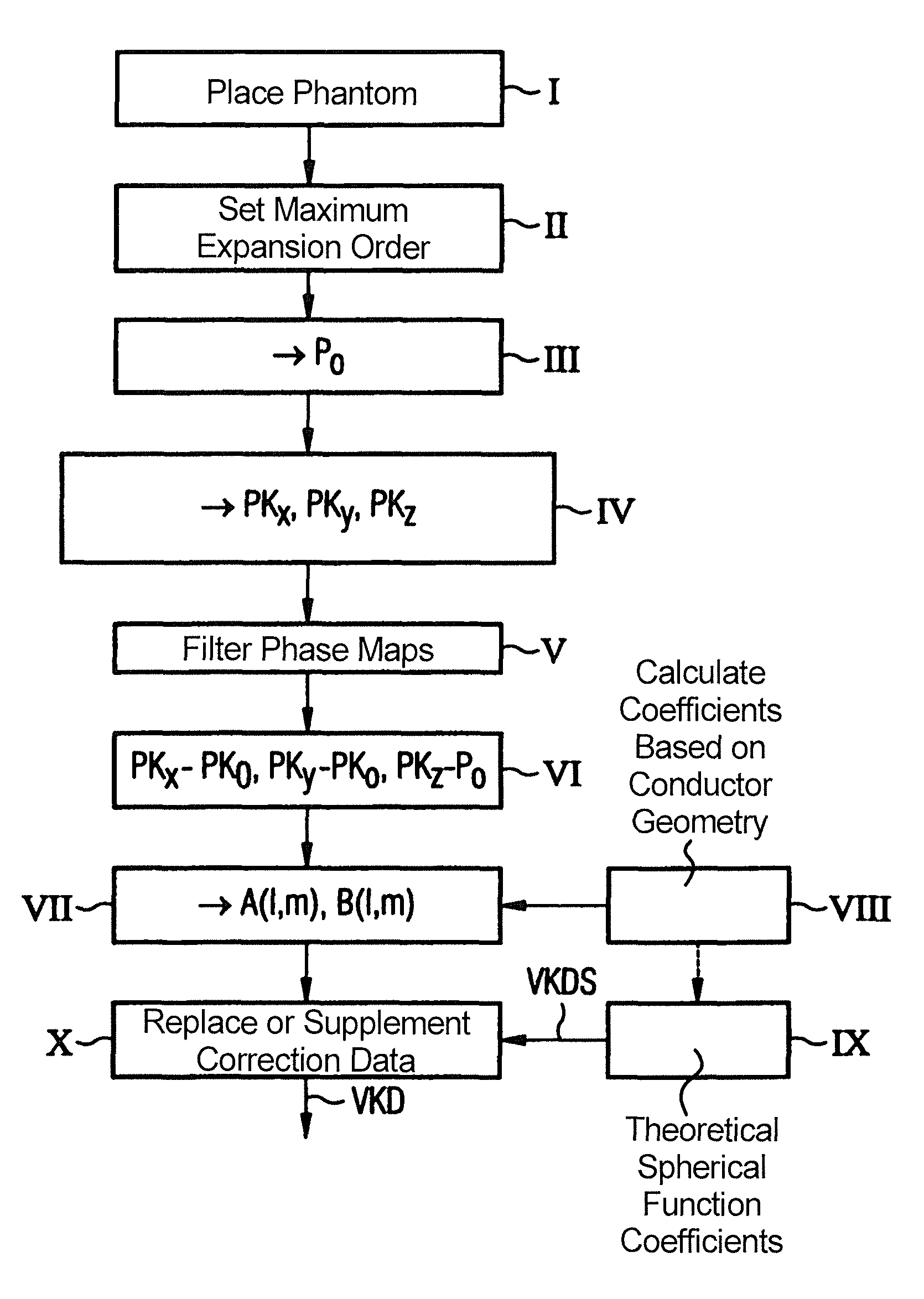
[0043]In the method shown in FIG. 1, all gradient coils are calibrated in one pass in order to then determine the spherical function coefficients and the distortion correction data based on these coefficients. Without limitation of generality, it is assumed that the phase maps already explained above are determined as parameter maps.

[0044]The method initially begins in Step I by positioning that a measurement phantom in the measurement space of the magnetic resonance scanner. This measurement phantom can be, for example, a spherical phantom, an ellipsoidal phantom, a cylindrical phantom or the like. A spherical phantom is advantageously used. The phantom is fashioned in a typical manner, for example is simply filled with water.

[0045]The maximum expansion order can be predetermined by the user in Step II. Moreover, at this point he can additionally also select the matrix size and the imaging volume (field of view=FoV). The matrix size indicates the number of voxels in the FoV, i.e. t...


PUM


Abstract

In a method and device to determine distortion correction data for distortion correction of magnetic resonance images acquired with a magnetic resonance system, a starting spherical function is calculated represents the magnetic field of a gradient coil of the magnetic resonance system on the basis of the conductor geometry of the gradient coil. A three-dimensional parameter map is determined that represents a magnetic field generated by the gradient coil using a defined measurement subject, with a defined gradient strength being set for the appertaining gradient coil. A deviation parameter map is generated on the basis of the parameter map and on the basis of a reference parameter map which was determined with deactivated gradient coil. Spherical function coefficients of the gradient magnetic field are determined by fitting a spherical function representing the magnetic field of the gradient coil to the deviation parameter map using the starting spherical function. The distortion correction data are determined on the basis of the spherical function coefficients of the fitted spherical function.

Description

BACKGROUND OF THE INVENTION[0001]1. Field of the Invention[0002]The invention concerns a method to determine distortion correction data for distortion correction of magnetic resonance images acquired with a magnetic resonance system, as well as a method to implement such a distortion correction. Moreover, the invention concerns a device to determine distortion correction data and a magnetic resonance system with such a device.[0003]2. Description of the Prior Art[0004]Magnetic resonance tomography is a widespread technique for acquisition of images of the inside of the body of a living examination subject. In order to acquire an image with this method, the body or a body part of the patient or test subject that is to be examined must initially be exposed to an optimally homogeneous, static basic magnetic field which is generated by a basic field magnet of the magnetic resonance system. During the acquisition of the magnetic resonance images, rapidly switched gradient fields that are...

Claims


Application Information

Patent Timeline
Patent Type & Authority Patents(United States)
IPC IPC(8): A61B6/03
CPCG01R33/443G01R33/56572G01R33/243
Inventor KIMMLINGEN, RALPHKREHER, SABRINAWEIDEMANN, ANDREAS
Owner SIEMENS HEALTHCARE GMBH
Why Eureka
Try Eureka