Method and apparatus for removing peripheral portion of a glass sheet

a technology of glass sheets and peripheral parts, applied in the field of glass sheet periphery finishing, can solve the problems of affecting the overall yield, affecting the quality of glass sheets, so as to achieve less surface slippage in scoring, improve surface quality, and improve the effect of surface quality

Inactive Publication Date: 2014-06-24
CORNING INC
View PDF6 Cites 1 Cited by
  • Summary
  • Abstract
  • Description
  • Claims
  • Application Information

AI Technical Summary

Benefits of technology

[0078]One or more embodiments and / or aspects of the present disclosure have the following advantages. First, by using a heating element to preferentially heat the peripheral portion having a bead region, the stress inside the glass sheet in the peripheral region can be significantly relieved, resulting in easier surface scoring, more uniform score-line, less surface slippage in scoring, and higher yield in the scoring step. The impact of bead heating on scoring is especially pronounced for thin glass sheets having a Th(C) of at most 500 μm, more advantageous for those having a Th(C) of at most 400 μm, still more advantageous for those having a Th(C) of at most 300 μm, still more advantageous for those having a Th(C) of at most 200 μm. Furthermore, the preferential heating of the bead region, by relieving the residual stress, results in an overall glass sheet with reduced warp, thereby facilitating the engagement of the ribbon surface with restraining devices, especially suction cups. The impact of preferential bead heating on scoring and sheet warp is especially pronounced for thin glass sheets having a Th(C) of at most 500 μm, more advantageous for those having a Th(C) of at most 400 μm, still more advantageous for those having a Th(C) of at most 300 μm, still more advantageous for those having a Th(C) of at most 200 μm. The thinner the glass, the more dramatic the impact of the residual stress on sheet shape is.

Problems solved by technology

Thus, the peripheral portions of both sides of an as-formed glass sheet obtained directly from the forming device, such as in the bottom-of-draw area of a fusion down-draw or slot down-draw process, sometimes called “beads,” tend to have lower surface quality than the center region of the major surfaces.
The present inventors have found that, for glass sheets with high flexibility, bead removal can be a significant challenge and an overall yield bottleneck in a glass sheet manufacture process.
Thus, an acceptable bead removal process for a glass sheet with relatively low flexibility may be unacceptable for a glass sheet with significantly higher flexibility.

Method used


Image

  • Method and apparatus for removing peripheral portion of a glass sheet
  • Method and apparatus for removing peripheral portion of a glass sheet
  • Method and apparatus for removing peripheral portion of a glass sheet

Examples


example 1

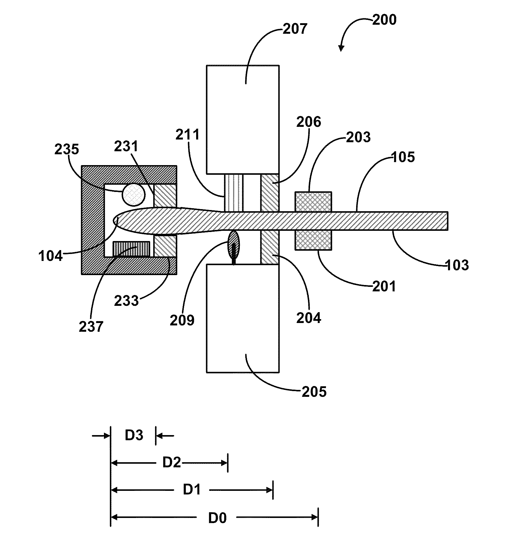
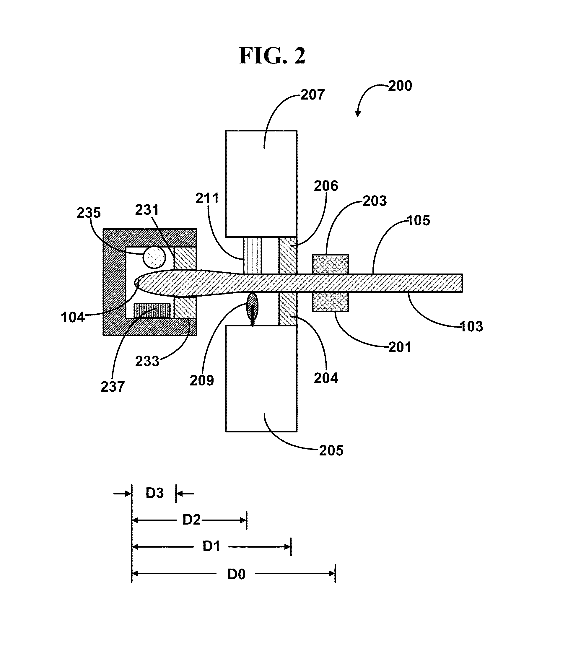
[0128]FIG. 2 schematically illustrates a cross-sectional view of one end of a glass sheet bead removing apparatus 200 in operation according to certain embodiments of the first and second aspects of the present disclosure. The other end, substantially symmetrical to the end illustrated, is not shown. The glass sheet shown in FIG. 1 is being secured by the two clamping arms 201, 203 of a clamp affixed to a suspension device (not shown) such as a vertical glass sheet suspension conveyor. Normally, the glass sheet is first engaged with the clamping arms 201 and 203 outside of the peripheral portion removing apparatus 200, and then moved into the apparatus 200 by the conveyor. Inside the peripheral portion removing apparatus 200, a first side edge restraining tower 205 comprising a first side edge restraining clamp strip 204 is located on the side of the first major surface 103 of the glass sheet, and a second side edge retraining tower 207 comprising a second side edge restraining clam...

example 2

[0130]FIG. 3 schematically illustrates a cross-sectional view of one end of a glass sheet bead removing apparatus 200 in operation according to another example. The other end, substantially symmetrical to the end shown, is not shown. In this example, the glass sheet shown in FIG. 1 is being secured by the two clamping arms 201, 203 of a clamp affixed to a suspension device (not shown) such as a vertical glass sheet suspension conveyor. Normally, the glass sheet is first engaged with the clamping arms 201 and 203 outside of the peripheral portion removing apparatus 200, and is then moved into the apparatus 200 by the conveyor. Inside the peripheral portion removing apparatus 200, a first side edge restraining tower 205 comprising a first side edge restraining clamp strip 204 is located on the side of the first major surface 103 of the glass sheet, and a second side edge retraining tower 207 comprising a second side edge restraining clamp strip 206 is located on the side of the second...

example 3

[0131]FIG. 4 schematically illustrates a cross-sectional view of one end of a glass sheet peripheral portion removing apparatus 400 in operation. The other end, being symmetrical, is not shown. As can be seen, compared to the apparatus 300 of FIG. 3, the apparatus 400 comprises suction cup(s) 215, but does not comprise the pushing bar 217. During operation, the first and second side edge restraining clamp strips 204 and 206 move towards each other once the glass sheet is positioned inside the apparatus 200, engage the glass sheet, restrain the portion of the glass sheet close to the bead region, and secure the glass sheet to enable the following steps. Once the glass sheet is clamped on both sides by the restraining towers (only one side shown in this figure), the heating bar 235 is turned on to preferentially heat the peripheral portion to a predetermined, desired temperature. Afterwards, a score-wheel 209, installed on the first side edge restraining tower 205, touches the first m...


PUM

PropertyMeasurementUnit
thicknessaaaaaaaaaa
thicknessaaaaaaaaaa
thicknessaaaaaaaaaa

Abstract

Process for removing peripheral portions such as bead regions of a glass sheet including a step of pushing the glass sheet in the peripheral portion using a pushing mechanism such as a pushing bar, and corresponding apparatus. As a result of the use of the pushing mechanism, the engagement completion time for suction cups, if used, are reduced significantly. A process without using suction cups is enabled with enhanced yield. The increased process stability and enlarged process window are particularly advantageous for processing glass sheets having high flexibility.

Description

FIELD[0001]The present invention relates to method and apparatus for glass sheet periphery finishing. In particular, the present invention relates to method and apparatus for removing a peripheral portion of a glass sheet. The present invention is useful, e.g., for removing the bead regions of a glass sheet formed from a down-draw process for use as glass substrates for displays.TECHNICAL BACKGROUND[0002]Thin glass sheets have found use in many optical, electronic or optoeletronic devices, such as liquid crystal displays (LCD), organic light-emitting diode (OLED) displays, solar cells, as semiconductor device substrates, color filter substrates, cover sheets, and the like. The thin glass sheets, having a thickness from several micrometers to several millimeters, may be fabricated by a number of methods, such as float process, fusion down-draw process (a method pioneered by Corning Incorporated, Corning, N.Y., U.S.A.), slot down-draw process, and the like.[0003]In many of the applica...

Claims


Application Information

Patent Timeline
Patent Type & Authority Patents(United States)
IPC IPC(8): B67B7/00
CPCC03B33/091C03B33/033Y10T225/12C03B33/09C03B33/0215Y10T225/321C03B33/0235B65G2249/04Y02P40/57
Inventor CAVALLARO, III, NICHOLAS DOMINICHILL, KEITH MITCHELLREIDY, HARRY JWANG, LIMINGZHENG, ZHEMINGZHOU, NAIYUE
Owner CORNING INC
Why Eureka
Try Eureka