
System and method for qualifying usability risk associated with subsurface defects in a multilayer coating

a multi-layer coating and usability risk technology, applied in the direction of instruments, machines/engines, optical radiation measurement, etc., can solve the problems of thermal barrier coating delamination or disbonding, thermal barrier coating stripping and replacement, and increased inspection time of hot gas path components

Active Publication Date: 2014-06-24
GENERAL ELECTRIC CO
View PDF25 Cites 17 Cited by
  • Summary
  • Abstract
  • Description
  • Claims
  • Application Information

AI Technical Summary

Benefits of technology

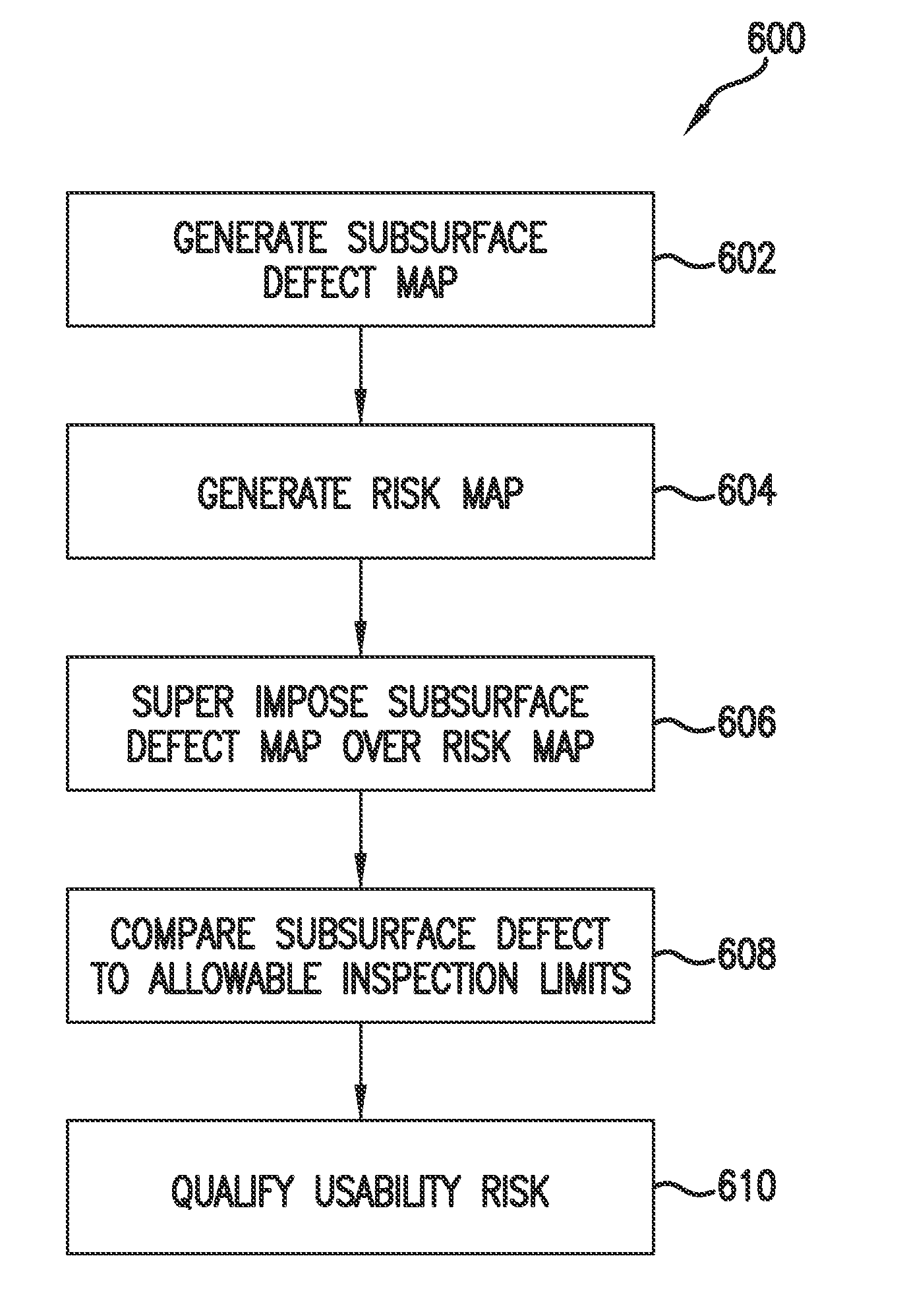
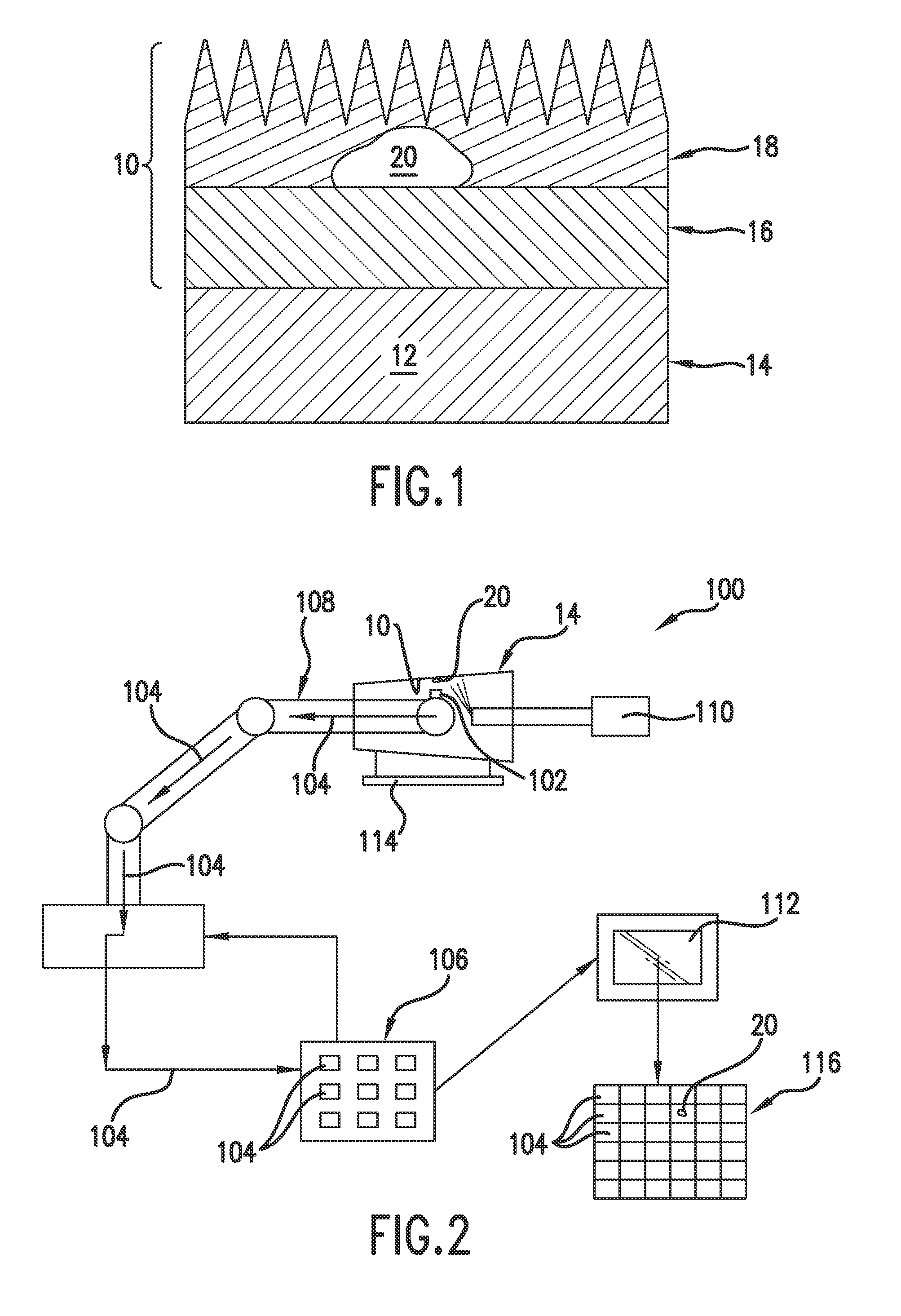
The present invention provides systems and methods for qualifying usability risks associated with subsurface defects in a thermal barrier coating of a hot gas path component. The system includes an infrared detection device and a processing unit that generates a subsurface defect map of the coating based on the infrared images. The system also includes a risk map of the hot gas path component and an overlay map that superimposes the subsurface defect map over the risk map to determine a risk level of the defect. Combining the subsurface defect with allowable inspection limits, the system qualifies usability risks associated with continued use of the thermal barrier coating. The technical effects of the invention include improved detection and qualification of subsurface defects in thermal barrier coatings, allowing for better maintenance and repair of hot gas path components.

Problems solved by technology

Despite great care taken during manufacture to ensure adhesion of the thermal insulation coat to the bond-coat, thermal cycling eventually leads to subsurface defects in the thermal barrier coating known as delamination or disbonding.
Delamination generally leads to spallation that eventually exposes the underlying alloy to extreme temperatures that may impact the durability of the liner and / or transition duct.
Typically, the thermal barrier coating is stripped and replaced after a pre-determined number of inspection cycles, in part due to limitations of many current inspection processes.
Removal and reapplication of the thermal barrier coating significantly increases the time required to inspect the hot gas path component and contributes substantially to the overall cost of inspection / repair.

Method used


Image

  • System and method for qualifying usability risk associated with subsurface defects in a multilayer coating
  • System and method for qualifying usability risk associated with subsurface defects in a multilayer coating
  • System and method for qualifying usability risk associated with subsurface defects in a multilayer coating

Examples


Embodiment Construction

[0022]Reference will now be made in detail to present embodiments of the invention, one or more examples of which are illustrated in the accompanying drawings. The detailed description uses numerical and letter designations to refer to features in the drawings. Like or similar designations in the drawings and description have been used to refer to like or similar parts of the invention. As used herein, the term “radially” refers to the relative direction that is substantially perpendicular to an axial centerline of a particular component, and the term “axially” refers to the relative direction that is substantially parallel to an axial centerline of a particular component.

[0023]Each example is provided by way of explanation of the invention, not limitation of the invention. In fact, it will be apparent to those skilled in the art that modifications and variations can be made in the present invention without departing from the scope or spirit thereof. For instance, features illustrat...


PUM


Abstract

A system for qualifying usability risk associated with subsurface defects in a multilayer coating includes a component having a multilayer coating, an infrared detection device for capturing infrared images of the multilayered coating and a processing unit that is in electronic communication with the infrared detection device where the processing unit generates a subsurface defect map of the multilayer coating based on the infrared images. The system further includes a risk map of the component.

Description

FIELD OF THE INVENTION[0001]The present invention relates to a system and a method for qualifying usability risk associated with subsurface defects in a multilayer coating. In particular, the present invention involves using infrared technology to determine size and location of subsurface defects in a multilayer coating such as a thermal barrier coating to qualify usability risk associated with continued use of the multilayer coating.BACKGROUND OF THE INVENTION[0002]A combustion section of a gas turbine generally includes a plurality of combustors that are arranged in an annular array around an outer casing such as a compressor discharge casing. Pressurized air flows from a compressor to the compressor discharge casing and is routed to each combustor. Fuel from a fuel nozzle is mixed with the pressurized air in each combustor to form a combustible mixture within a primary combustion zone of the combustor. The combustible mixture is burned to produce hot combustion gases having a hig...

Claims


Application Information

Patent Timeline
IPC IPC(8): G01N25/00G01N21/88G01J5/02
CPCG01N21/88G01N25/72F01D5/288F01D21/003G01N2021/8427G01N2021/8438G01N2021/8864
Inventor WOODS, STEVEN CHARLESBAUMMER, JAMES CARROLL
Owner GENERAL ELECTRIC CO
Learn More