Pulse modulated PIM measurement instrument

a measurement instrument and pulse technology, applied in the direction of instruments, process and machine control, line-transmission details, etc., can solve the problems of interference with system operation, unwanted signals, and troublesome combined 3sup>rd /sup>order response, etc., to achieve significant power saving, weight reduction, and size reduction

Active Publication Date: 2014-06-24
ANRITSU CO
View PDF12 Cites 26 Cited by
  • Summary
  • Abstract
  • Description
  • Claims
  • Application Information

AI Technical Summary

Benefits of technology

[0018]By controlling the duty cycle of the PWM to limit ON time of the HPAs relative to OFF time, significant power savings and weight reduction can occur. Size is reduced because heat sinks and other cooling components are not required to dissipate power. Without the cooling components the power amplifiers and duplexers can be significantly lighter. With significantly lower power requirements and minimal sized parts, the PIM measurement system can be portable and battery operated.

Problems solved by technology

PIM has surfaced as a problem for cellular telephone technologies such as Global System for Mobile Communications (GSM), Advanced Wireless Service (AWS) and Personal Communication Service (PCS) systems.
Cable assemblies connecting a base station to an antenna on a tower using these cellular systems typically have multiple connectors that cause PIMs that can interfere with system operation.
When these multiple signals are allowed to share the same signal path in a nonlinear transmission medium, the unwanted signals can occur.
The combined 3rd order response is particularly troublesome as it produces an unwanted signal at 2F1-F2 that can pass from one system transmitter into another system's receiver.
If they are allowed to combine without isolation, intermodulations would appear due to power output stage nonlinearities.
This translates to a continuous DC power consumption of 200 to 250 Watts.

Method used


Image

  • Pulse modulated PIM measurement instrument
  • Pulse modulated PIM measurement instrument
  • Pulse modulated PIM measurement instrument

Examples


Embodiment Construction

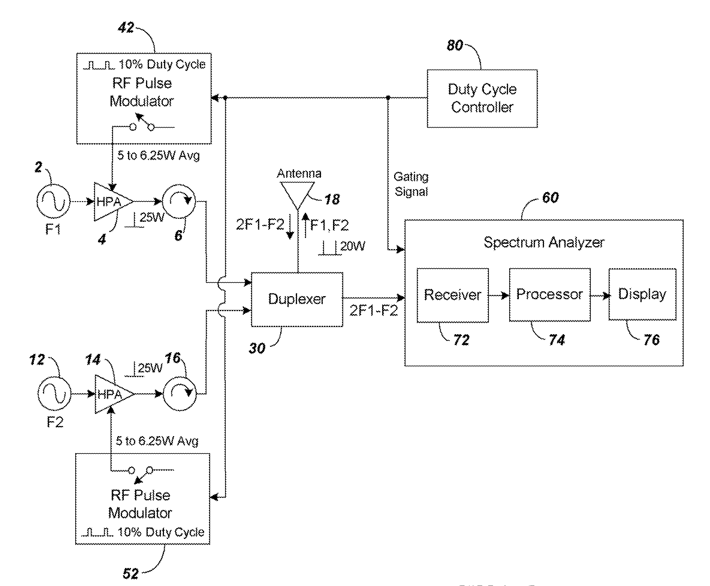
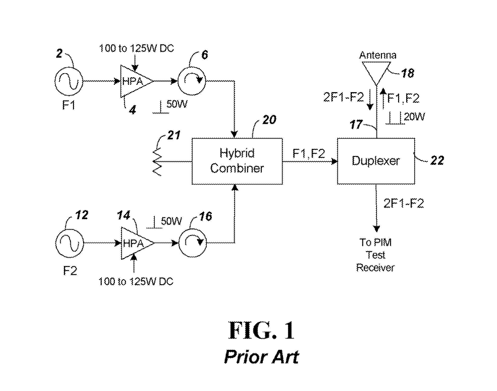
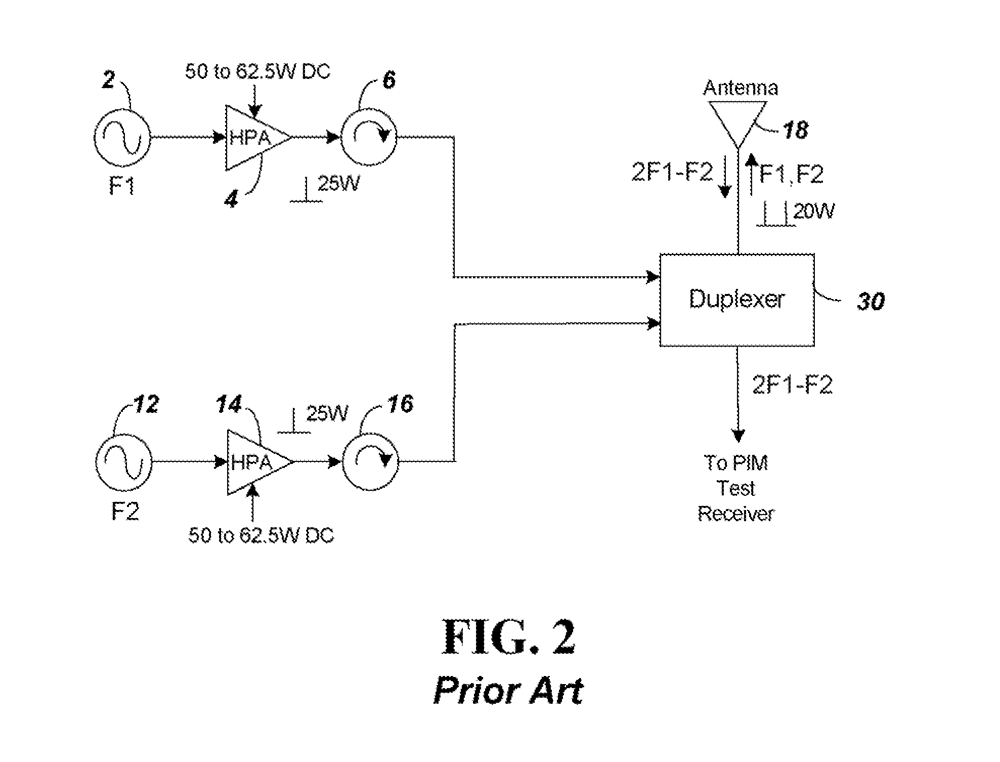
[0024]FIG. 3 shows a PIM test circuit according to embodiments of the present invention. The circuit of FIG. 3 modifies the circuitry of FIG. 2 by adding pulse width modulators 42 and 52 to provide DC power to the amplifiers 4 and 14. The pulse width modulators 42 and 52 create a reduction of DC Power by the ratio of their ON to OFF time. Although the pulse width modulators 42 and 52 are shown in FIG. 3 added to the circuitry of FIG. 2, it is understood that similar pulse width modulators could be used with the circuitry of FIG. 1 to obtain a power savings.

[0025]The duty cycle for the pulse width modulators is selected to set the DC power consumption. For example, a duty cycle of 10% will reduce the total average power consumption down to 10% of the amount without modulating the peak output power. For the 100-125 average Watts consumed in the circuit of FIG. 1, by supplying power to power amplifiers 4 and 14 with pulse width modulators having a 10% duty cycle, average power consumed...


PUM


Abstract

A device to measure a passive intermodulation (PIM) creating component is provided that uses minimal average power. For a PIM measurement, two separate signals F1 and F2 are generated to simulate signals, such as from two different types of cell phone operating bands being transmitted in the same area or two different transmit frequencies within one cell phone operating band. PIMs are measured to assure interference is not created on one of the cell phone bands. Minimal power is used by connecting pulse width modulators (PWM) to provide DC power to the high power amplifiers (HPA) creating the signals F1 and F2. By controlling the duty cycle of the PWM to limit ON time of the HPAs to approximately 10%, significant average power savings occur. Size is also reduced with reduced power consumption because heat sinks and other cooling components are not required.

Description

BACKGROUND[0001]1. Technical Field[0002]The present invention relates to a passive intermodulation (PIM) measurement instrument with circuitry configured to reduce average DC power needed during operation.[0003]2. Related Art[0004]A PIM is an unwanted signal or signals generated by the non-linear mixing of two or more frequencies in a passive device such as a connector or cable. PIM has surfaced as a problem for cellular telephone technologies such as Global System for Mobile Communications (GSM), Advanced Wireless Service (AWS) and Personal Communication Service (PCS) systems. Cable assemblies connecting a base station to an antenna on a tower using these cellular systems typically have multiple connectors that cause PIMs that can interfere with system operation.[0005]The PIM signals are created when two signals from the same or different systems mix at a PIM point such as a faulty cable connector. If the generated PIM harmonic frequency components fall within the receive band of a...

Claims


Application Information

Patent Timeline
Patent Type & Authority Patents(United States)
IPC IPC(8): G05F1/613G01R23/14G05F1/00G01R7/00
CPCG01R7/00G05F1/00G05F1/613G01R23/14H04B3/46
Inventor BRADLEY, DONALD, ANTHONY
Owner ANRITSU CO
Why Eureka
Try Eureka