Clamping device and workpiece conveying robot

a technology of workpiece and conveying robot, which is applied in transportation and packaging, hoisting equipment, manufacturing tools, etc., can solve the problems of workpiece space apprehension, and achieve the effect of high positional precision, high positional precision and high positional precision

Inactive Publication Date: 2014-07-01
SINFONIA TECHNOLOGY CO LTD
View PDF7 Cites 400 Cited by
  • Summary
  • Abstract
  • Description
  • Claims
  • Application Information

AI Technical Summary

Benefits of technology

[0025]In order to make it possible to attain that the advantageous effects described above more significantly it is preferable that a shape of a workpiece targeted to be retained be a specific shape, and it is preferable that the workpiece be formed in the shape of a disk of which a side face is defined as an outer circumferential face.
[0026]Furthermore, the workpiece conveying robot of the present invention is characterized in that a hand portion is provided with the clamping device described above. With such a configuration, a workpiece can be retained with a high positional precision and with a great force of retention, which is strong relative to a vibration, and the workpiece can be delivered by performing release of retention while maintaining a high positional precision after the workpiece has been conveyed to a predetermined conveyance destination.ADVANTAGEOUS EFFECTS
[0027]According to the present invention described above, there can be provided a clamping device and a workpiece conveying robot that are capable of retaining a workpiece with a high positional precision and releasing the retention of the workpiece while maintaining the positional precision, that are further having a strong force of retention relative to a vibration as well.

Problems solved by technology

However, the clamping device (a substrate retaining device) described in Granted Japanese Patent No. 4600856 performs positioning by means of the stationary clamp on the distal end side and the movable clamp on the proximal end side when retaining a workpiece and thus there is an apprehension that the workpiece is spaced from the stationary clamp on the proximal end side.

Method used


Image

  • Clamping device and workpiece conveying robot
  • Clamping device and workpiece conveying robot
  • Clamping device and workpiece conveying robot

Examples


Embodiment Construction

[0040]Hereinafter, an embodiment of the present invention will be described with reference to the drawings.

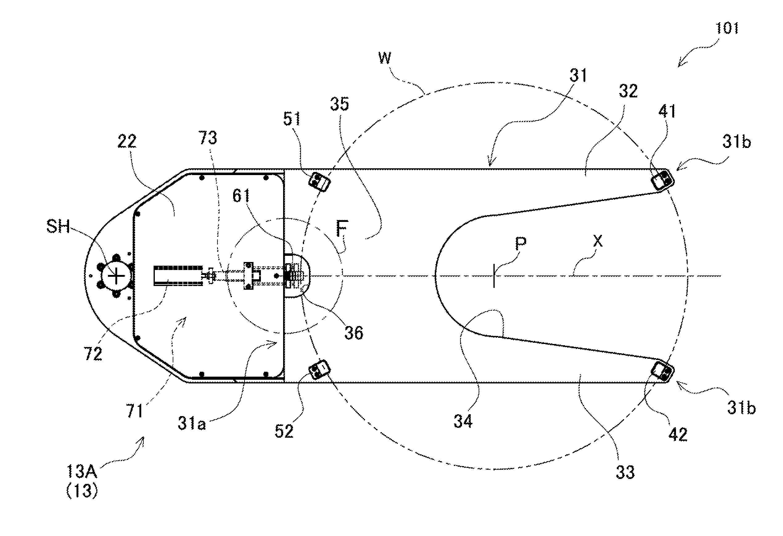
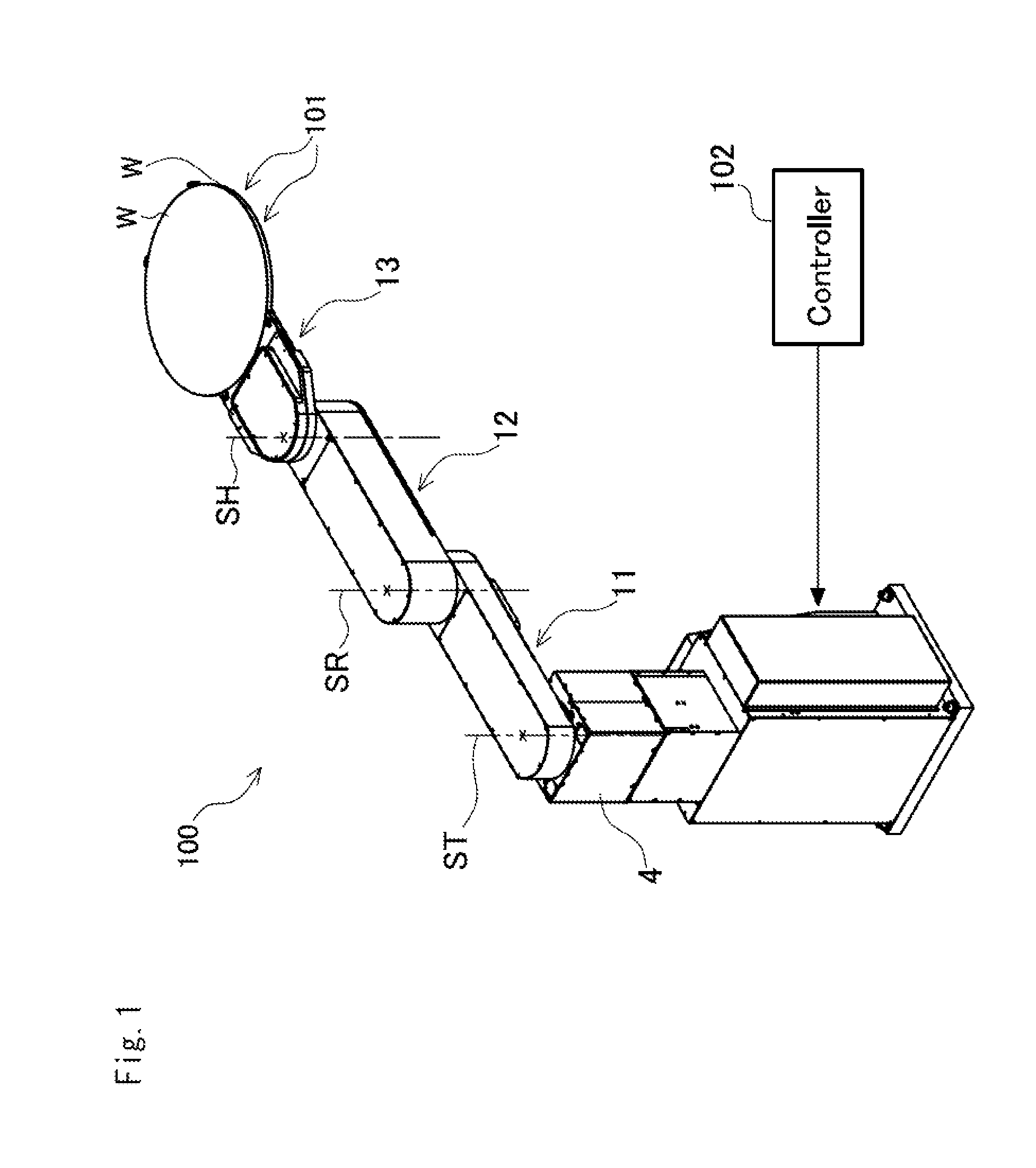
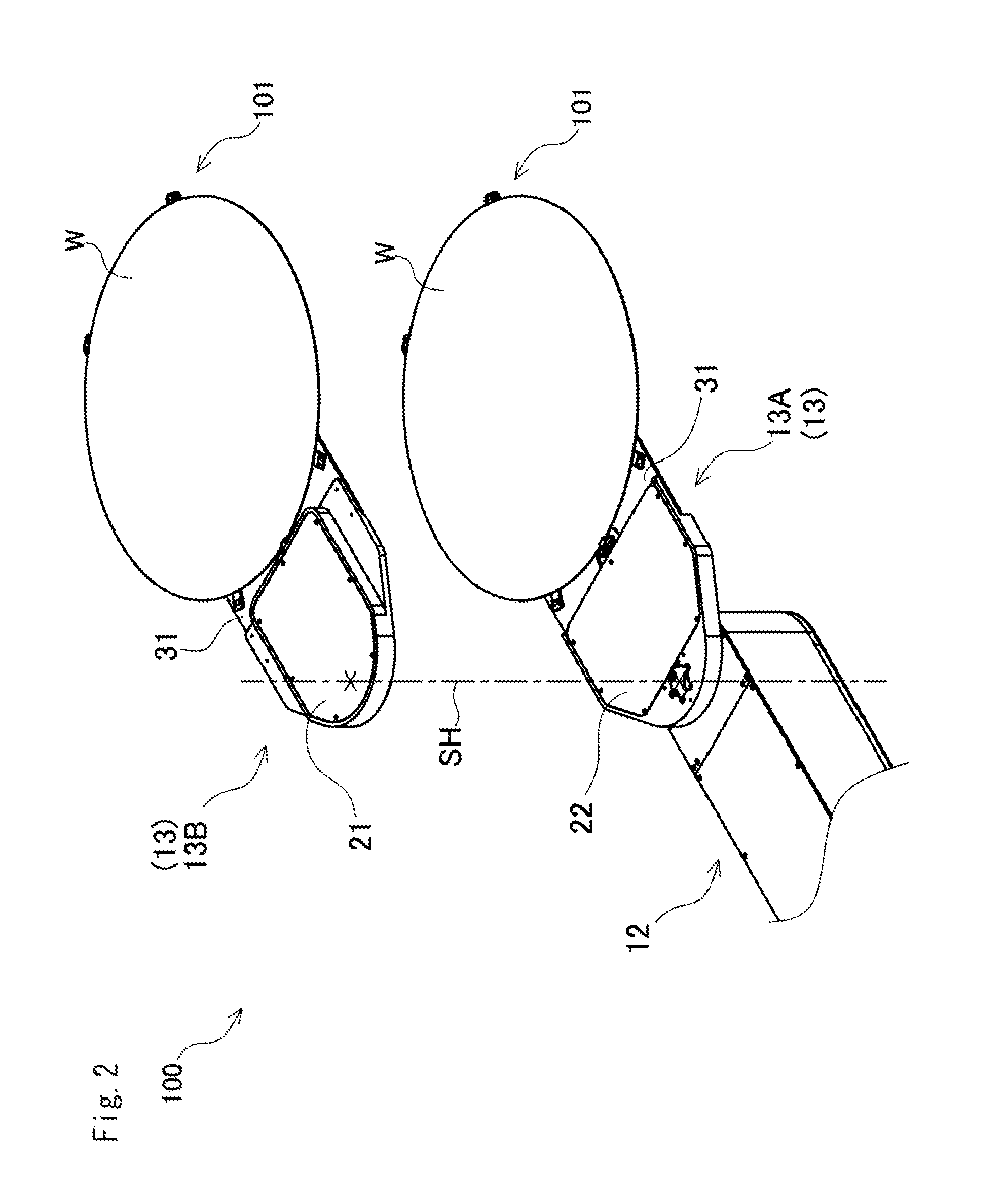
[0041]FIG. 1 shows a workpiece conveying robot 100 in the embodiment. This workpiece conveying robot 100 is capable of receiving a workpiece W formed in the shape of a disk such as a semiconductor wafer and then conveying and delivering the received workpiece to a device in a next step. In the drawings employed for illustration in the embodiment, same reference numerals are assigned to same constituent elements of the conventional clamp device illustrated using FIG. 11 and FIG. 12. In addition, in the following description, a side face of a workpiece W designates an outer circumferential face of a disk.

[0042]As shown in FIG. 1, this workpiece conveying robot 100 is configured as a robot of a horizontal joint type having three joints, and relative to a base 4, a first arm element 11, a second arm element 12, and a hand portion 13 are provided so as to be sequentially relatively ...


PUM


Abstract

A clamping device comprising: a distal end side stationary blocks which are provided on a side of a distal end of a workpiece retaining base, and in which stationary tilt faces tilting downwardly to a central direction of the workpiece are formed; a proximal end side stationary blocks which are provided on a side of a proximal end of the workpiece retaining base, and in which upward stationary tilt faces tilting downward toward the central direction of the workpiece are formed; and a movable block which is arranged at a position proximal to the proximal end side stationary blocks, and is capable of advancing to or retracting from a side of the distal end side stationary blocks with the workpiece being held between the blocks, and in which a downward movable tilt face tilting upwardly toward the central direction of the workpiece is formed.

Description

CROSS REFERENCE TO RELATED APPLICATIONS[0001]This application claims priority of Japanese Patent Application No. 2012-232378 filed on Oct. 19, 2012. The contents of the application are incorporated herein by reference in their entirety.BACKGROUND OF THE INVENTION[0002]1. Field of the Invention[0003]The present invention relates to a clamping device for retaining a workpiece when conveying the workpiece needed to be positioned with a high precision and a workpiece conveying robot including the clamping device.[0004]2. Description of the Related Art[0005]Conventionally, in order to convey workpieces such as semiconductor wafers or glass substrates, there is used a workpiece conveying robot for retaining and conveying these workpieces on a hand portion.[0006]In the case of applying precision processing to such workpieces, a workpiece conveying robot is needed to deliver these workpieces to a device in a next step with a high positional precision. Thus, the workpiece conveying robot is ...

Claims


Application Information

Patent Timeline
Patent Type & Authority Patents(United States)
IPC IPC(8): B66C1/42
CPCB25J15/0042B25J15/0028B25J15/0014B65G49/07Y10S901/31H01L21/68707B25J15/08
Inventor URABE, YUJIMIENO, YASUMICHI
Owner SINFONIA TECHNOLOGY CO LTD
Why Eureka
Try Eureka