Device, system and method for compression treatment of a body part

a body part and compression technology, applied in the field of body part compression treatment devices, can solve the problems of short battery life, affecting the operation of the device, and requiring a complex locking mechanism, and achieve the effect of increasing the force capacity of the actuation unit, eliminating or substantially reducing the engagement of the force transfer devi

Active Publication Date: 2014-07-01
SWELLING SOLUTIONS
View PDF134 Cites 26 Cited by
  • Summary
  • Abstract
  • Description
  • Claims
  • Application Information

AI Technical Summary

Benefits of technology

[0016]One particular objective is to provide a device for compression treatment of a body part, having an improved power to weight ratio.
[0077]According to a fifth principle, the actuator may be arranged to cause the gripping member to perform a reciprocating motion, having a component in a plane substantially parallel with an intended direction of movement of the movable member, whereby said rectifying means are provided for: providing a high friction between the gripping member and the movable member during a first part of said reciprocating motion, wherein the gripping member moves in a first direction in said plane, and providing low friction between the gripping member and the movable member during a second part of said reciprocating motion, wherein the gripping member moves in a second, opposite direction.

Problems solved by technology

The motor of US 2004 / 0073146 A1 is of an electromagnetic type, which provides low power to weight ratio, and thereby a very bulky device.
When combined with the low efficiency of the disclosed motors and power transmission elements, the result is a short battery life.
Furthermore, the device would require a complex locking mechanism for holding the pressure during a period longer than that of the reciprocating motion.
Also, due to the torque capabilities of conventional electromagnetic motors, it would be difficult to meet the force requirements for Deep Vein Thrombosis prophylaxis using this technology and in a compact format.
Furthermore, as the reciprocating motion is produced through an intermediate mechanism and the tissue mechanics of every patient are different, there will be little to no control of the actual force output applied by the straps onto the patient.
The ends of the cuff are attached to each other such that electrical activation of actuators of the cuff will cause it to constrict.
The device of US 2002 / 0173735 A1 is only suitable for impulse applications, since the solenoid actuator cannot be made to retain a force for a period longer than that of the reciprocating motion, since a very high current would be required to provide for low frequency or static operation.
This device also provides low power to weight ratio, resulting in a heavy device.
Furthermore, the device is only capable of providing small motions, due to the tight fitting requirements of the cuff.
Furthermore, solenoid actuators are only capable of providing small motions, thereby placing tight fitting requirements on the cuff.
Motion limitations of the actuators will also limit the actual forces that one can apply to the patient as the patient's tissue compliance will have to be overcome to reach significant force levels.
The use of pneumatic actuation as disclosed in U.S. Pat. No. 6,494,852 B1 also provides low power to weight ratio and thereby makes the device bulky.
Furthermore, efficiency of pneumatic devices is low, as they waste much energy in their compressors, valves, accumulators, conduits, and bladder expansion, in addition to wasting energy on each deflation cycle by venting the compressed air to the surroundings.
Hence, such a device requires an oversized power unit and will provide short battery lives.
The use of pneumatic bladders also results in bulky, non-breathable garments around the patient's limb.
These devices generally require large amounts of active material, and are therefore at present only suitable for high-cost applications.
Some of the concepts shown in these documents also require active materials having properties that cannot be achieved in large scale production or cannot be maintained over many actuation cycles with known materials.
Each of the configurations of the prior art would place undue burden on the active material properties.
Therefore either excessive material or very high performance material is needed for the devices, leading to both high cost devices and increased reliability and safety issues in practical devices.

Method used


Image

  • Device, system and method for compression treatment of a body part
  • Device, system and method for compression treatment of a body part
  • Device, system and method for compression treatment of a body part

Examples


first embodiment

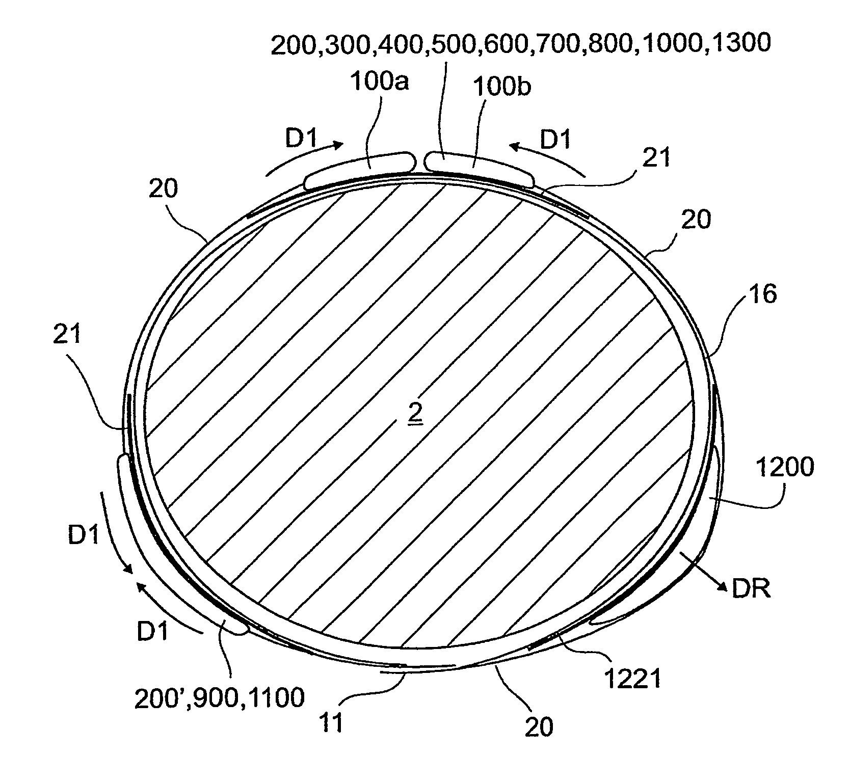
[0220]FIG. 3 is a schematic sectional view of an actuation unit 100 which may be arranged as indicated in FIGS. 1a-1d, 2 and 4. As a non-limiting example, this embodiment may be provided using a resonant active material multiple electroded bender. In such a device, recitfication may be achieved by a friction interface. The actuation unit 100 may extend in a direction perpendicular to the section, along the entire or part of the compression device 1.

[0221]The actuation unit 100 comprises a housing 107a, 107b, wherein a first part 107a of the housing holds a flexible substrate 102, on which an actuator 101 is arranged. The actuator has a gripping member 106 protruding from the actuator and towards the second part 107b of the housing. The second part of the housing holds a bias spring 103.

[0222]A movable member 120, which may be integrated with or connected to the compression member, is clamped between the bias spring 103 and the gripping member 106. The flexible substrate 102 may be ...

second embodiment

[0234]FIGS. 5a-5c schematically illustrate an actuation unit 200 in which a power transmission mechanism 208 is provided between a gripping member 206 and a spindle 209, upon which a compression member 220, or a connection member, connected to the compression member 220, is wound. The actuator of

[0235]FIGS. 5a-5c may use a resonant active material, such as piezoceramics, e.g. in the form of a multiple electroded stack or bulk material driven at a suitable resonant or anti-resonant frequency. FIG. 5a illustrates one half of the actuation unit 200, which may be symmetric about the line of symmetry L. The actuator 201 with the electrode sets 204, 205 and bias springs 203 may be provided in a housing 207, similar to the embodiment of FIG. 3.

[0236]However, instead of the gripping member 206 acting directly upon the compression member 220, the gripping member 206 acts upon a contact surface 210 of a wheel 208 or disc shaped structure. Hence, the wheel 208 forms a movable member. The cont...

third embodiment

[0242]FIGS. 6a and 6b schematically illustrate part of an actuation unit 300 the actuator of which can be provided by a resonant motion amplification mechanism utilizing multiple vibration modes or coupled vibration modes of a resonant horn or actuator.

[0243]In FIGS. 6a and 6b, the housing has been left out for clarity. A pair of actuators 301a, 301b, have been arranged with a respective fastening point 311 to a housing or frame of the actuation unit 300, and connected to an amplifying structure 312, which may be e.g. a micro-molded horn of metal or low acoustic loss polymer. The horn may have one or more further fastening points to the housing or frame of the actuation unit 300.

[0244]Furthermore, the amplifying structure 312 may be provided with a gripping member 306, which is to interact with a movable member 320, which may be the compression member or a connection member connected thereto. A bias spring 303 may be arranged between a fastening point 313 and the movable member 320...


PUM


Abstract

A device for compressive treatment of a body part includes a compression member, adapted to at least partly encircle the body part, and an actuation unit, arranged to tighten the compression member to provide a compressive force to the body part. The actuation unit includes an active material actuator. There is also disclosed a system comprising such a device and methods for its therapeutic, cosmetic and non-therapeutic use and operation.

Description

[0001]This application is a national stage filing under 35 U.S.C. §371 of International Application No. PCT / EP2006 / 000276, filed on Jan. 13, 2006, the contents of which are incorporated herein by reference.TECHNICAL FIELD[0002]The present disclosure relates to a device for compression treatment of a body part. The disclosure also relates to a system for compression treatment, comprising such a device and to a method of compression treatment, using such a device.[0003]The disclosure further relates to actuators that can be used in the device for compression treatment, but also in other applications where a strap is to be tightened around an object.BACKGROUND[0004]Compression therapies may be used for treatment and / or prophylaxis of a number of conditions, including, but not limited to, Deep Vein Thrombosis (DVT), vascular disorders, circulatory disorders, edemas, heart conditions (treated by counterpulsation), lymphedema, burns and embolisms. Other areas of use may be stress therapy,...

Claims


Application Information

Patent Timeline
Patent Type & Authority Patents(United States)
IPC IPC(8): A61H19/00A61H7/00
CPCA61H23/0254A61H2205/10A61H1/008A61F13/085A61H2201/5071A61H2209/00A61H2201/1642A61H2201/0111A61H2201/1207A61H2201/1654A61H2201/1688A61H2201/1697A61H2230/30A61H2201/149A61H11/00A61H2011/005A61H2201/1215A61H2201/1695A61H2201/5061
Inventor TOTH, LANDY
Owner SWELLING SOLUTIONS
Why Eureka
Try Eureka