Radiation imaging apparatus and image processing method

a radiation imaging and image processing technology, applied in the field of radiation imaging apparatus, can solve the problems of high cost, complex apparatus, insufficient contrast of images, etc., and achieve the effect of high image quality

Inactive Publication Date: 2014-07-01
FUJIFILM CORP
View PDF6 Cites 47 Cited by
  • Summary
  • Abstract
  • Description
  • Claims
  • Application Information

AI Technical Summary

Benefits of technology

[0016]An object of the present invention is to provide a radiation imaging apparatus and an image processing method capable of producing a differential phase image with high image quality from a single moiré image.
[0026]The first grid may be an absorption grid or a phase grid for allowing the incident radiation to cause Talbot effect and producing the first periodic pattern image.

Problems solved by technology

Because the intensity changes of the X-rays caused by living soft tissue and soft matter are small, their images do not have sufficient contrast.
A difference in X-ray absorption power between the cartilaginous part and the synovial fluid is small, resulting in poor contrast of the image.
This makes the apparatus complex and incurs high cost.
The motions of the subject and the grids during the series of image captures may degrade image quality of the differential phase image.
In the Fourier transform method disclosed in U.S. Pat. No. 8,340,243, a peak position of a carrier frequency component cannot be obtained accurately because the distortion in the moiré fringes of the moiré image in a direction of a period or fringes, due to distortion, an arrangement error, or the like of the first and second grids, spreads the carrier frequency, and this causes a degradation of the image quality of the differential phase image.
Hence, the resolution in the frequency space decreases and the image quality of the differential phase image degrades when the X-ray image detector has a small number of pixels.

Method used


Image

  • Radiation imaging apparatus and image processing method
  • Radiation imaging apparatus and image processing method
  • Radiation imaging apparatus and image processing method

Examples


first embodiment

(First Embodiment)

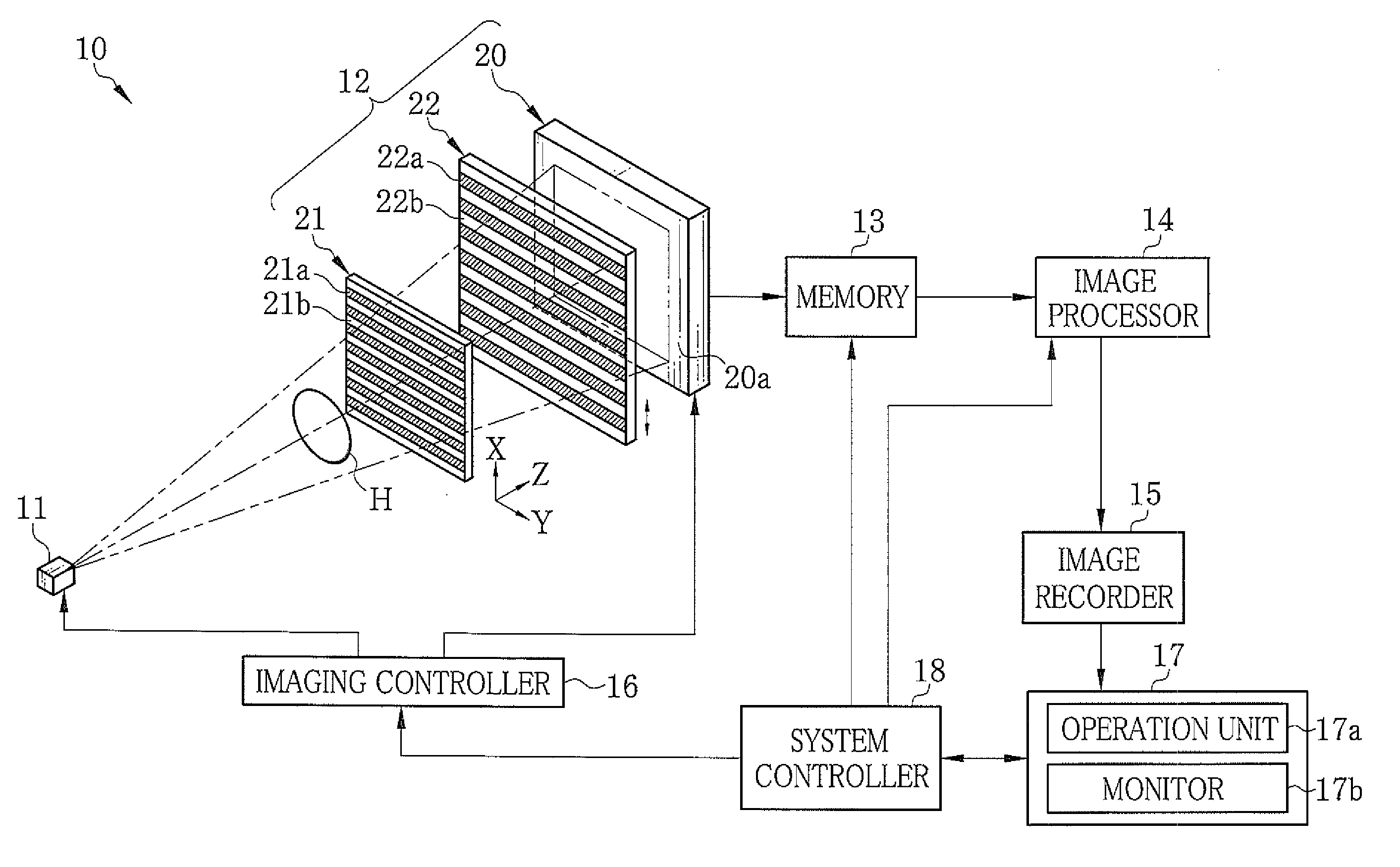
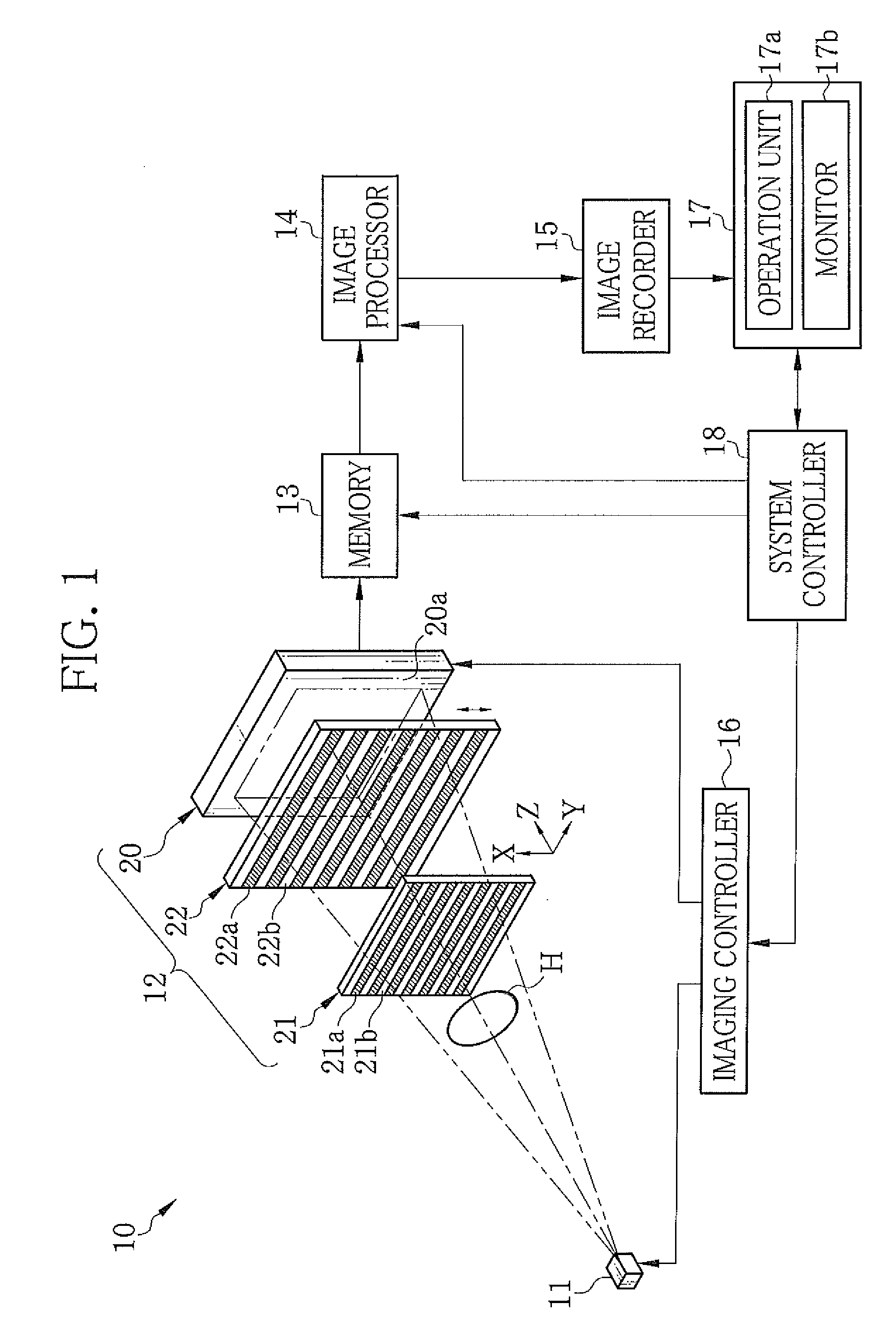
[0050]In FIG. 1, an X-ray imaging apparatus 10 comprises an X-ray source 11, an imaging unit 12, a memory 13, an image processor 14, an image recorder 15, an imaging controller 16, a console 17, and a system controller 18. As is well known, the X-ray source 11 has a rotating anode type X-ray tube (not shown) and a collimator (not shown) for restricting an X-ray emission field. The X-ray source 11 emits X-rays to a subject H.

[0051]The imaging unit 12 comprises an X-ray image detector 20, a first grid 21, and a second grid 22. The first and second grids 21 and 22 are absorption grids and disposed to oppose the X-ray source 11 relative to a Z direction, being an X-ray emission direction. There is a space enough to place the subject H between the X-ray source 11 and the first grid 21. The X-ray image detector 20 is a flat panel detector using a semiconductor circuit. The X-ray image detector 20 is disposed behind and close to the second grid 22. A detection surface 20a...

second embodiment

(Second Embodiment)

[0103]Next, a second embodiment of the present invention is described. In the above-described first embodiment, the relative tilt of the first and second grids 21 and 22 in the direction within the grid plane causes moiré fringes MS in the G2 image. In the second embodiment, the first and second grids 21 and 22 are not tilted. Instead, a positional relation (the distances L1 and L2) between the first and second grids 21 and 22, or the grid pitches p1 and p2 of the first and second grids 21 and 22 are adjusted to be slightly different from the relation represented by the mathematical expression (1). Thereby, the moiré fringes MS occur in the G2 image as shown in FIG. 12.

[0104]The pattern period p3 in the X direction of the G1 image at the position of the second grid 22 is slightly shifted from the grid pitch p2 of the second grid 22. The moiré fringes MS have a period T in the X direction. The period T is represented by a mathematical expression (15) below.

[0105]T=...

third embodiment

(Third Embodiment)

[0114]Next, a third embodiment of the present invention is described. In the first and second embodiments, the X-ray source 11 has the single focal point. In the third embodiment, as shown in FIG. 14, a multi-slit (source grid) 23 disclosed in WO2006 / 131235 or the like is disposed in front of the X-ray source 11 on the emission side. Similar to the first and second grids 21 and 22, the multi-slit 23 has a plurality of X-ray absorbing portions 23a and a plurality of X-ray transmitting portions 23b, extending in the Y direction and arranged alternately in the X direction. The grid pitch p0 of the multi-slit 23 is set to substantially satisfy a mathematical expression (19) below, where “L0” denotes a distance between the multi-slit 23 and the first grid 21.

[0115]p0=L0L2⁢p2(19)

[0116]The radiation from the X-ray source 11 is dispersed in the Y direction such that the each X-ray transmitting portion 23b functions as the small (narrow) X-ray focal point. The radiation app...


PUM

PropertyMeasurementUnit
widthaaaaaaaaaa
thicknessaaaaaaaaaa
thicknessaaaaaaaaaa

Abstract

An X-ray imaging apparatus comprises a first grid, a second grid, and an X-ray image detector. The first grid passes X-rays emitted from an X-ray source and produces a first periodic pattern image. The second grid opposes the first grid. The second grid partly blocks the first periodic pattern image and produces a second periodic pattern image with moiré fringes. The X-ray image detector detects the second periodic pattern image and produces image data. The X-ray image detector has pixels arranged in two dimensions in X and Y directions. The M pixels arranged in the Y direction form one group. The group is shifted in the Y direction by the number of the pixels less than M each time. A phase of an intensity modulated signal, composed of pixel values of the pixels in the each shifted group, is calculated. Thereby a differential phase image is produced.

Description

CROSS REFERENCE TO RELATED APPLICATIONS[0001]This non-provisional application is a Continuation of International Application No. PCT / JP2012 / 059071 filed on Apr. 03, 2012, which claims the benefit of Japanese Patent Application Nos. 2011-093691 filed on Apr. 20, 2011 and 2011-264692 filed on Dec. 02, 2011, both are filed in Japan. The entire contents of all of the above applications are hereby incorporated by reference.BACKGROUND OF THE INVENTION[0002]1. Field of the Invention[0003]The present invention relates to a radiation imaging apparatus for obtaining an image based on a phase shift of radiation and an image processing method for a radiation imaging apparatus.[0004]2. Description Related to the Prior Art[0005]Radiation, for example, X-rays have a characteristic that they attenuate depending on atomic number of an element constituting a substance and density and thickness of the substance. Due to this characteristic, the X-rays are used as a probe for inspecting inside of a subj...

Claims


Application Information

Patent Timeline
Patent Type & Authority Patents(United States)
IPC IPC(8): G01N23/04
CPCA61B6/484A61B6/4035A61B6/4291
Inventor HASHIMOTO, ATSUSHITADA, TAKUJIMURAKOSHI, DAI
Owner FUJIFILM CORP
Why Eureka
Try Eureka