
Auto-synchronous fluorescence detection method and apparatus

a fluorescence detection and auto-synchronous technology, applied in the direction of photometry, lighting and heating apparatus, converting sensor output, etc., can solve the problems of obscuring or diminishing the visibility of synthetic fluorescent probes, losing much of their discriminatory power in the presence of autofluorescence,

Active Publication Date: 2014-07-15
CONNALLY RUSSELL
View PDF11 Cites 2 Cited by
  • Summary
  • Abstract
  • Description
  • Claims
  • Application Information

AI Technical Summary

Benefits of technology

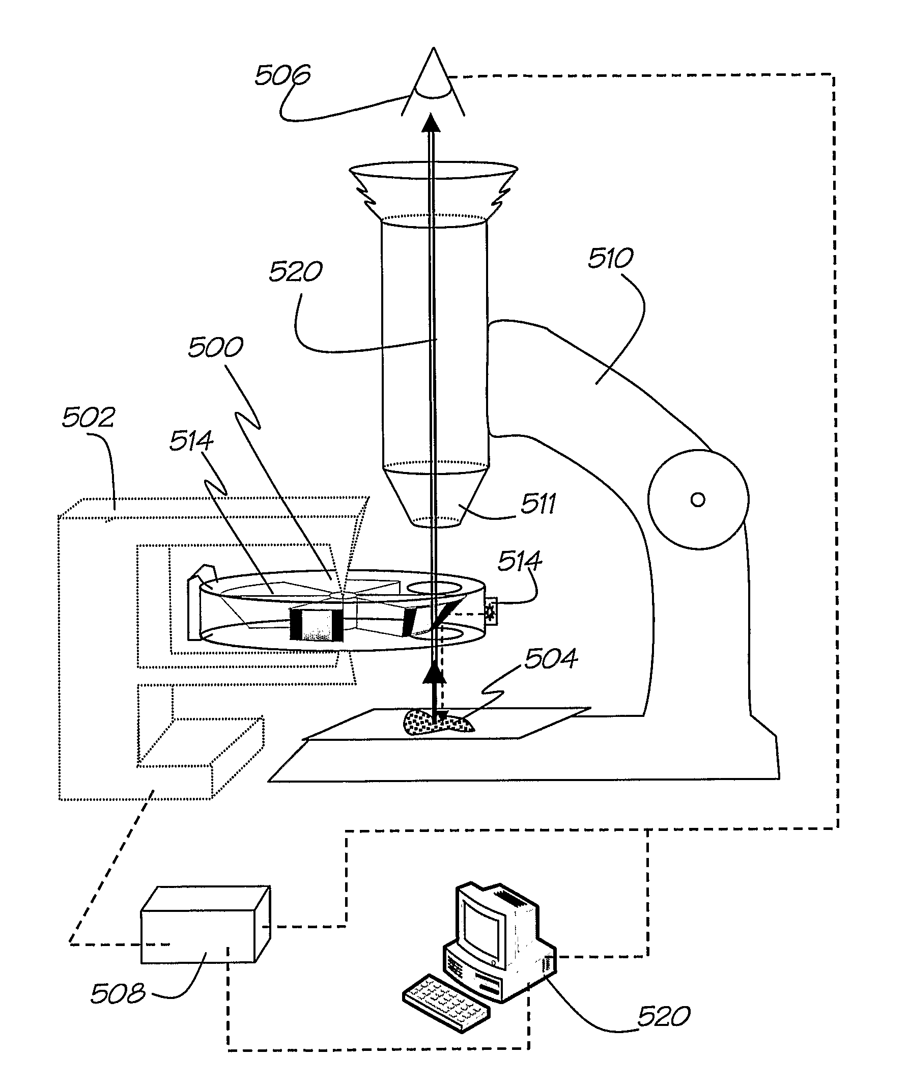
The patent describes a device, method, and system for detecting light emissions from a sample using a microscope system. The device includes a second communication portion that creates a separate optical path for detecting the desired light emissions, while preventing other optical communications from occurring simultaneously. This leads to a simpler and less expensive device for TGL, which can be used in microscope systems.

Problems solved by technology

Fluorescence methods afford a sensitive means for the detection of single molecules, however, fluorescent probes (also referred to as fluorescent markers), used to “label” a particular feature in a sample (for example a particular organism or bio-molecule such as Giardia in a water sample) to determine the presence and / or number of features in the sample, lose much of their discriminatory power in the presence of autofluorescence.
Organic and inorganic autofluorophores are ubiquitous in nature and some materials fluoresce with great intensity, obscuring or diminishing the visibility of synthetic fluorescent probes.
Spectral selection techniques (emission and excitation filters) can reduce the problem but are not always applicable due to the abundance and spectral range of autofluorescence.
There are instances where the detection of rare-event signals using conventional fluorescence techniques is exceedingly difficult (or impossible) and consequently, where TGL microscopy has greatest utility.
TGL microscopes were built to exploit these novel compounds however various deficiencies in the instrumentation and luminescent probes resulted in relatively insensitive instruments.
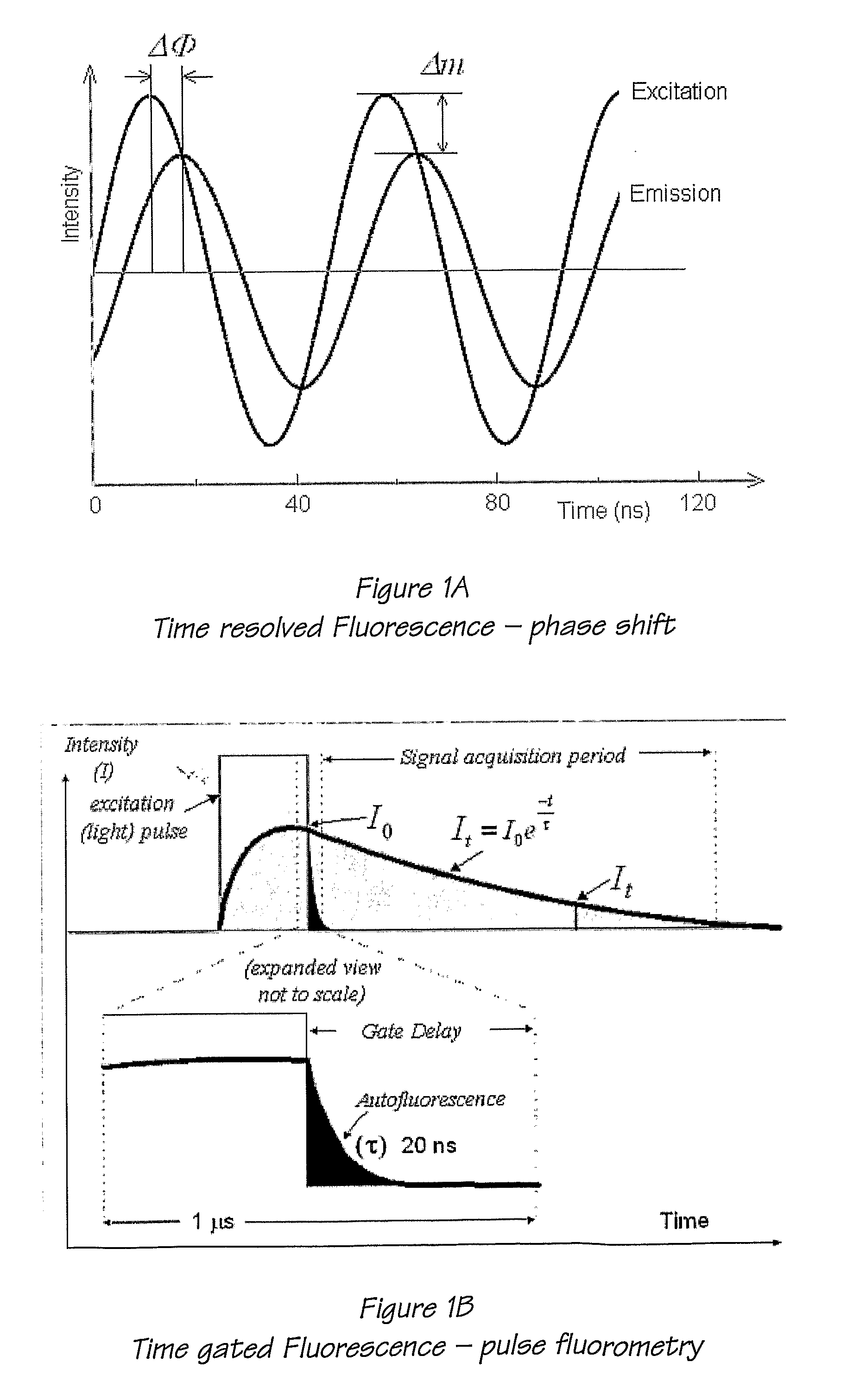
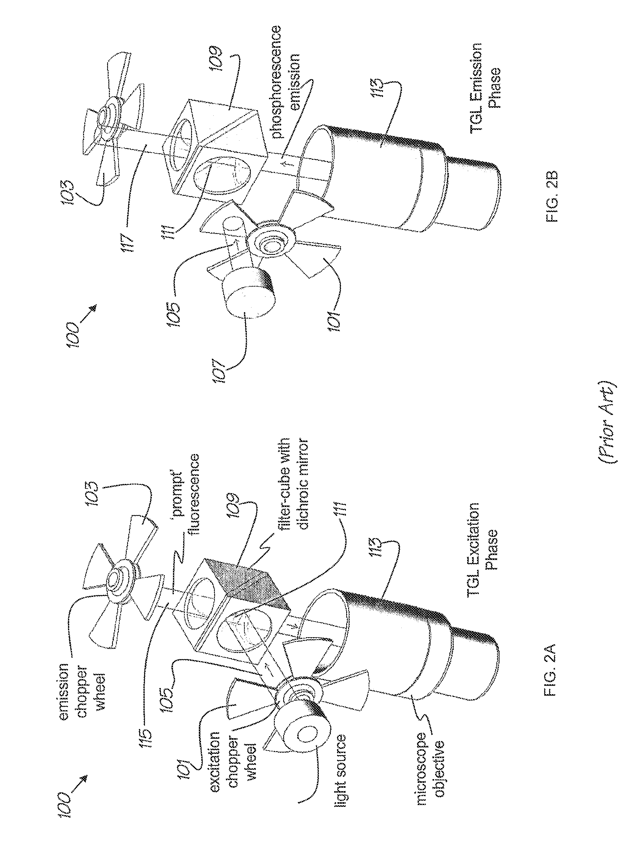
Unfortunately, the gate-delays typical for chopper based switching mechanisms are quite long (about 20 to 500 μs) in comparison to the emission decay time of the fluorescent labels and therefore the fluorescence has typically decayed quite significantly before the detection state is able to commence.
Also, conventional time-gated luminescence microscopes incur substantial losses both during the excitation and emission / detection states as light passages through the dichroic filter cube.
The dichroic mirror in the filter cube also has significant limitations on the particular wavelengths that are allowed to be either reflected on to the sample or to pass through to be detected due to the limitations in coating designs.
Thus, such systems have severe limitations on the number of allowed wavelengths and the reflection / transmission bandwidth of the design wavelengths that are able to be utilised for the detection system.
Such dichroic filter cubes are also expensive and complex to interchange causing significant barriers to the use of the TGL microscope system for different excitation sources or luminescent probes with different operating wavelengths.
Whilst effective, the FELC shutters imposed a substantial insertion loss with transmission reduced to just 15% when fully open.
A further limitation of chopper excitation schemes arises from the relatively slow rise and fall time of the pulse (for example, in the systems described by Verwoerd et al, the rise / fall time was 50 to 100 μs at a chopper rotation speed of 3,800 rpm).
Excitation pulses with slow falling edges force extension of the gate-delay that leads ultimately, to a loss in SNR.
To achieve this, complex electronic phase matching circuitry and control systems are required, which are both expensive to implement and maintain.
Furthermore, the detector systems that must be used with these TGL microscope systems are prohibitively expensive (typical cost of a TGL EMCCD detector at the time of writing is in the range of about $20,000 to $45,000).
The prohibitive cost of such systems means that they are not available on a large scale since only the most well-funded research facilities can purchase and maintain such items.

Method used


Image

  • Auto-synchronous fluorescence detection method and apparatus
  • Auto-synchronous fluorescence detection method and apparatus
  • Auto-synchronous fluorescence detection method and apparatus

Examples


Embodiment Construction

[0182]Referring to FIG. 3A, there is provided an arrangement 200 of an apparatus for use in a time gated luminescence detection system. The apparatus 200 comprises

[0183]a) a first communication portion 204 for providing a first optical communication path between an illumination source location and a sample location;

[0184]b) a second communication portion 206 for (i) providing a second optical communication path between the sample location and the detection location, the second communication portion being operable to enable detection at the detection location of a desired optical emission from an illuminated sample which in use is located at the sample location via the second optical communication path; and (ii) concurrently preventing optical communication on the first optical communication path; and

[0185]c) a gate portion 214 for gating the first and second optical communication paths;

[0186]the apparatus 200 being capable of being arranged to provide the first optical communication...


PUM

PropertyMeasurementUnit
emission decay timeaaaaaaaaaa
optical wavelengthsaaaaaaaaaa

Abstract

An apparatus for time-gated fluorescence or luminescence detection includes gating means (206) arranged to alternately permit light from an excitation source (242) to be directed to a sample (235) along a first communication path (231, 232), and then permit light emitted from the sample to be directed to a detector (246) along a second communication path (237, 238) while blocking the first communication path (231, 232): The gating means (206) may comprise a single chopper wheel or apertured disc, or a rotating or oscillating arm, and may further comprise one or more reflective facets (207). The gating means (206) may be driven via a magnetic rotor, with a ferrite bead placed to offset rotor magnets with respect to drive coils, when at rest, so as to assist with self starting.

Description

CROSS REFERENCE TO RELATED APPLICATION[0001]This application is a national stage filing under 35 U.S.C. §371 of International Application No. PCT / AU2009 / 000596, filed May 13, 2009, which is hereby incorporated by reference in its entirety.TECHNICAL FIELD[0002]The present invention relates to time gated luminescence detection schemes and in particular to apparatus and methods for providing a time gated luminescence detection system.[0003]The invention has been developed primarily for use as apparatus methods, and systems for provision of auto-synchronous time gated luminescence detection schemes and microscope systems and will be described hereinafter with reference to this application. However, it will be appreciated that the invention is not limited to this particular field of use.BACKGROUND OF THE INVENTION[0004]Any discussion of the background art throughout the specification should in no way be considered as an admission that such background art is prior art, nor that such backg...

Claims


Application Information

Patent Timeline
Patent Type & Authority Patents(United States)
IPC IPC(8): G01N21/64G02B21/16G02B26/04
CPCG01N21/6458G01N21/6408G01N2021/6463G02B21/16G02B26/04
Inventor CONNALLY, RUSSELL
Owner CONNALLY RUSSELL
Learn More