Method for cutting materials using a laser beam

Inactive Publication Date: 2014-07-29
FRAUNHOFER GESELLSCHAFT ZUR FOERDERUNG DER ANGEWANDTEN FORSCHUNG EV
View PDF15 Cites 0 Cited by
  • Summary
  • Abstract
  • Description
  • Claims
  • Application Information

AI Technical Summary

Benefits of technology

[0021]It is the object of the present invention to develop a method for cutting by means of laser radiation of the above-mentioned type in such a way that higher cutting speeds can be

Problems solved by technology

The whisker formation observed at an excessively high cutt

Method used


Image

  • Method for cutting materials using a laser beam
  • Method for cutting materials using a laser beam
  • Method for cutting materials using a laser beam

Examples


Embodiment Construction

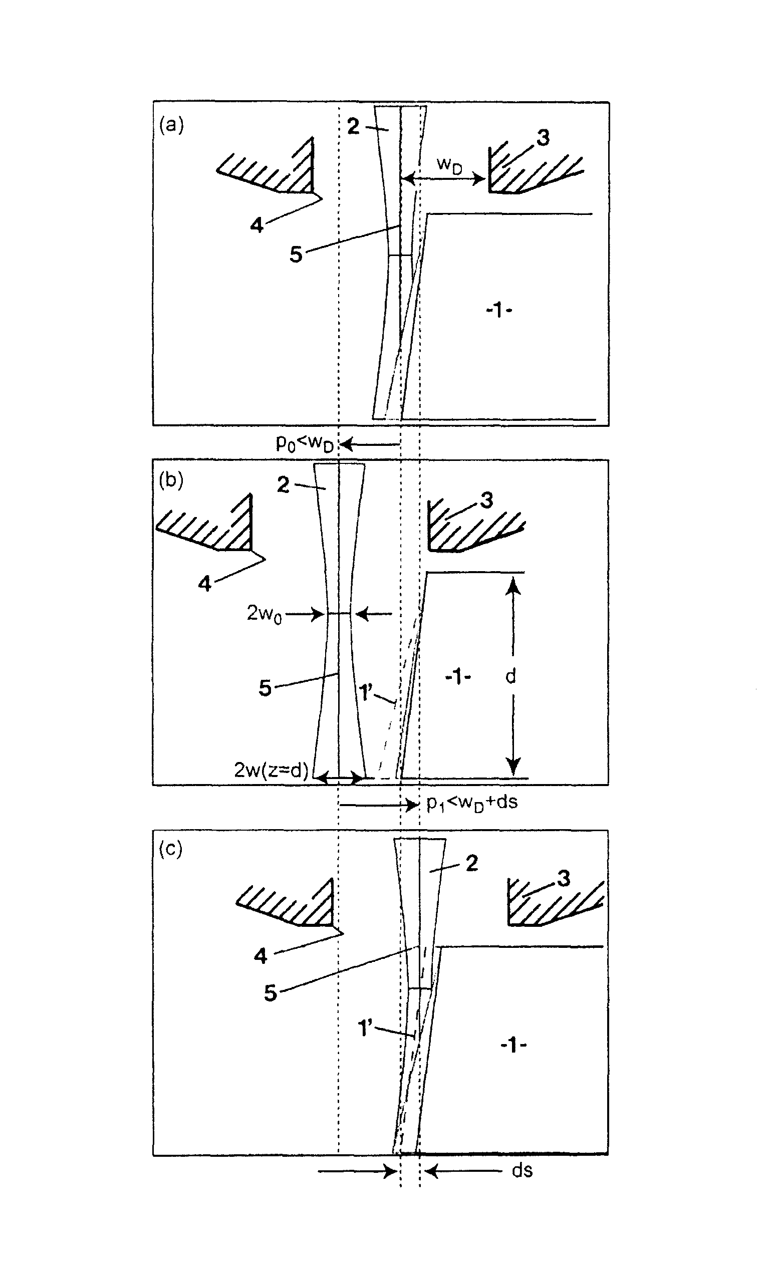
[0065]The preferred embodiments of the present invention will now be described with reference to FIGS. 1-4 of the drawings. Identical elements in the various figures are designated with the same reference numerals.

[0066]FIGS. 1(a) through 1(c) schematically show, in four phases, the modulation of the cutting head. Such a modulation of the cutting head is already sufficient for achieving an increased cutting speed and for cutting increased sheet thicknesses and for accomplishing a high-quality cut edge with little ripple or whisker formation and virtually no oxidation on the cut edge.

[0067]FIG. 1 shows the workpiece to be cut or separated with reference numeral 1. As indicated in FIG. 1(b), this workpiece 1 has a thickness d. The laser beam, designated by 2, exits out of a cutting head 3 of a laser cutting machine, which is not shown in greater detail. The inner radius WD of the cutting gas nozzle at the nozzle outlet, which is indicated in FIG. 1(a), is defined by the inner edge 4 o...


PUM

PropertyMeasurementUnit
Fractionaaaaaaaaaa
Lengthaaaaaaaaaa
Thicknessaaaaaaaaaa

Abstract

This invention relates to a method for cutting materials using a laser beam, which emerges from a cutting head comprising a cutting nozzle with an inner edge, and is absorbed by the cutting front. The axis of the laser beam is displaced in relation to a workpiece along a cutting line with a fixed orientation in the cutting direction of said workpiece. In this method the position (p) of the cutting head is modulated with regard to its time averaged value, or the laser power and gas pressure in the cutting head are modulated.

Description

BACKGROUND OF THE INVENTION[0001]The present invention relates to a method for cutting materials using a laser beam, which emerges from a cutting head comprising a cutting nozzle with an inner edge and is absorbed on the cutting front, the axis of the laser beam being moved along a cutting line with a fixed orientation in the cutting direction of a workpiece relative to said workpiece.[0002]The cutting of a workpiece with a laser beam is an established cutting method. It assumes a leading function among the laser-supported manufacturing methods in industrial applications. One demand continuously made by the users is enhanced efficiency of the method while the quality requirements are increasing.[0003]Essential features that must be guaranteed in fusion cutting, which includes laser beam cutting, are efficiency of the process, quality of the cut edge, ripple amplitude as small as possible, no formation of adherent drosses and no oxidation.[0004]Likewise, shorter processing times and ...

Claims


Application Information

Patent Timeline
IPC IPC(8): B23K26/38B23K26/14
CPCB23K26/1405B23K26/38B23K26/14B23K26/0626B23K26/142
Inventor SCHULZ, WOLFGANGPOPRAWE, REINHARTKAIERLE, STEFANPETRING, DIRK
Owner FRAUNHOFER GESELLSCHAFT ZUR FOERDERUNG DER ANGEWANDTEN FORSCHUNG EV
Why Eureka
Try Eureka