A tool system for ultra-high-speed cutting of CNC machine tools

A technology of CNC machine tool and cutting tool system, which is applied in the direction of manufacturing tools, metal processing machinery parts, metal processing equipment, etc., can solve the problem of inability to meet the requirements of ultra-high speed cutting speed, low moving speed of machine tool spindle feed system, and low speed of CNC machine tool spindle and other issues, to achieve great social and economic benefits, good processing effect, and fill the technical gap

Active Publication Date: 2018-10-19
TIANJIN POLYTECHNIC UNIV
View PDF6 Cites 0 Cited by
  • Summary
  • Abstract
  • Description
  • Claims
  • Application Information

AI Technical Summary

Problems solved by technology

At present, the main problem restricting the development of ultra-high-speed cutting technology is that the rotational speed of the machine tool spindle and the moving speed of the feed system are relatively low, which cannot meet the speed requirements of ultra-high-speed cutting.
[0004] In order to solve technical bottlenecks such as low spindle speed, poor cutting effect, low processing efficiency, and low manufacturing precision in the existing prior art CNC machine tools, the present invention proposes a tool system and implementation method for ultra-high-speed cutting of CNC machine tools. Fast, high cutting efficiency, good parts processing effect, high surface precision, beautiful appearance, can not only meet the actual engineering needs of ultra-high-speed precision machining, fill the gaps in related technologies, but also generate greater social and economic benefits

Method used


Image

  • A tool system for ultra-high-speed cutting of CNC machine tools
  • A tool system for ultra-high-speed cutting of CNC machine tools

Examples


Embodiment Construction

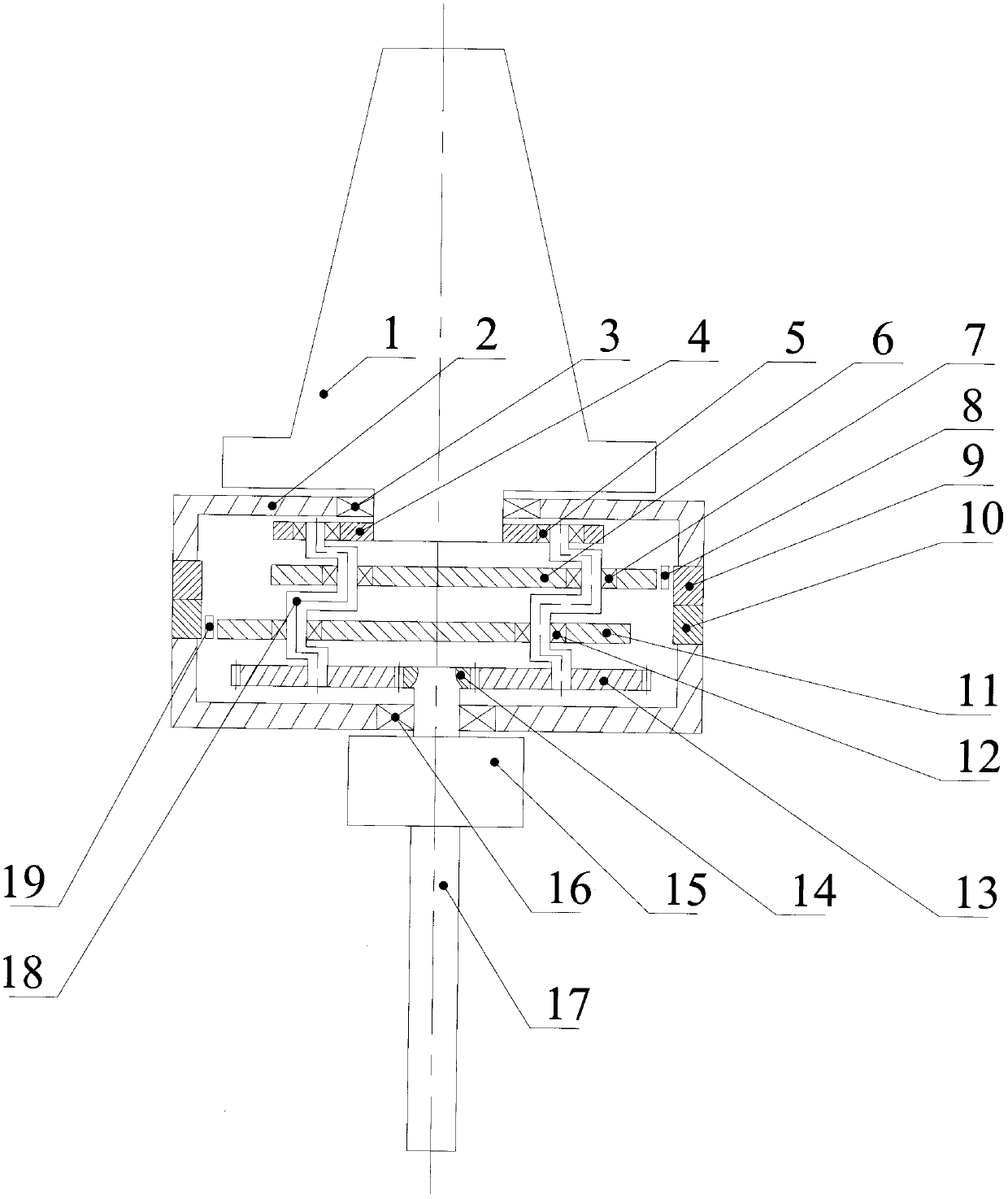
[0018] Embodiments of the present invention are described with reference to the accompanying drawings, below in conjunction with figure 1 , figure 2 The present invention will be specifically described. The upper end of the main shaft 1 is installed on the existing CNC machine tool. The machine tool transmits the existing rotational speed to the main shaft 1 to drive the main shaft 1 to rotate. At this time, the rotational speed of the main shaft 1 is relatively low. On the housing 2, the main shaft 1 is connected with the turret 4, and the main shaft 1 drives the turret 4 to rotate synchronously. Revolution, crankshaft 18 is an eccentric shaft, and the middle part of crankshaft 18 is equipped with epicycloid wheel A 6, cycloid wheel bearing A 7), epicycloid wheel B 11 and cycloid wheel bearing B 12, crankshaft 18 drives epicycloid wheel A 6 and the epicycloid wheel B 11 rotate, and the hypocycloid wheel A 9 and the hypocycloid wheel B 10 matched with the epicycloid wheel A...


PUM


Abstract

The invention discloses a cutter system for super-speed cutting of a numerically-controlled machine tool. The system comprises a main shaft, a housing, a locking sleeve and a cutter. The system is characterized in that the upper end of the main shaft is connected with the numerically-controlled machine tool; an input bearing is mounted at the lower end of the main shaft and positioned on the housing; the main shaft is connected with a rotating frame, and a crankshaft is mounted on the rotating frame; an epicycloidal wheel and a cycloidal wheel bearing are mounted in the middle part of the crankshaft, and a planet gear which is engaged with a sun gear is mounted at the lower end of the crankshaft; an output bearing is mounted on the sun gear and positioned on the housing; the sun gear is connected with the upper end of the locking sleeve, and the lower end of the locking sleeve is connected with the cutter. The system has the beneficial effects that the cutting rotation speed is extremely high during the processing of aviation and precision optical devices; the processing effect is good; the processing accuracy is high; extremely high surface roughness can be obtained; the actual engineering requirement of high-speed cutting can be met; the technological gaps can be filled; and moreover, the social benefit and the economic benefit are high.

Description

technical field [0001] The invention relates to the field of advanced manufacturing technology, in particular to a tool system for ultra-high-speed cutting of a numerical control machine tool. Background technique [0002] Ultra-high-speed cutting technology is generally considered to be an advanced manufacturing technology that cuts parts at a speed 10 times higher than conventional ones. The research results show that when the cutting speed is increased by 10 times and the feed rate is increased by 20 times, the cutting mechanism has undergone a fundamental change, and the cutting effect has also been greatly improved. The metal removal rate per unit power has increased by 30%-40%, and the cutting force has decreased. 30%, the cutting life of the tool has increased by 70%, the cutting heat left in the workpiece has been greatly reduced, the cutting vibration has almost disappeared, and the cutting process has undergone a substantial leap. A series of problems that have be...

Claims


Application Information

Patent Timeline
Patent Type & Authority Patents(China)
IPC IPC(8): B23Q5/04
CPCB23Q5/04
Inventor 莫帅马帅金国光吕超孙大明卞景扬赵念选孙泽豪韩涵尚新雨
Owner TIANJIN POLYTECHNIC UNIV
Why Eureka
Try Eureka