
Strut and a gas turbine structure comprising the strut

a gas turbine and strut technology, which is applied in the direction of liquid fuel engines, machines/engines, efficient propulsion technologies, etc., can solve the problems of reducing the efficiency of the engine, generating a distortion of the flow, and affecting the gas flow through the turbine, so as to reduce the impact on the gas flow, the effect of less efficiency and reducing the flow distortion

Active Publication Date: 2014-08-05
GKN AEROSPACE SWEDEN AB
View PDF8 Cites 22 Cited by
  • Summary
  • Abstract
  • Description
  • Claims
  • Application Information

AI Technical Summary

Benefits of technology

This design reduces flow distortion and enhances the efficiency of the gas turbine by minimizing the impact of struts on the gas flow, eliminating the negative effects of sharp fillet radii and maintaining a smooth curvature, thus improving overall engine performance.

Problems solved by technology

The indentations in the outer ring creates a disturbance to the gas flow through the turbine, which reduces the efficiency of the engine.
An area with a sharp fillet radius generates a local turbulent flow which has a negative impact on the disturbance on the gas flow through the turbine.
Small radii of the outer surface of a strut, which radii are present in a flow channel where the struts may be mounted, will generate a distortion of the flow.
The distortion of the flow may in turn lead to that an engine where the flow channel is included becomes less efficient.
In particular small radii in an area that are somewhat distant to the ends of the struts at a connection between the strut and an inner and outer ring respectively will lead to flow distortion.

Method used


Image

  • Strut and a gas turbine structure comprising the strut
  • Strut and a gas turbine structure comprising the strut
  • Strut and a gas turbine structure comprising the strut

Examples


Embodiment Construction

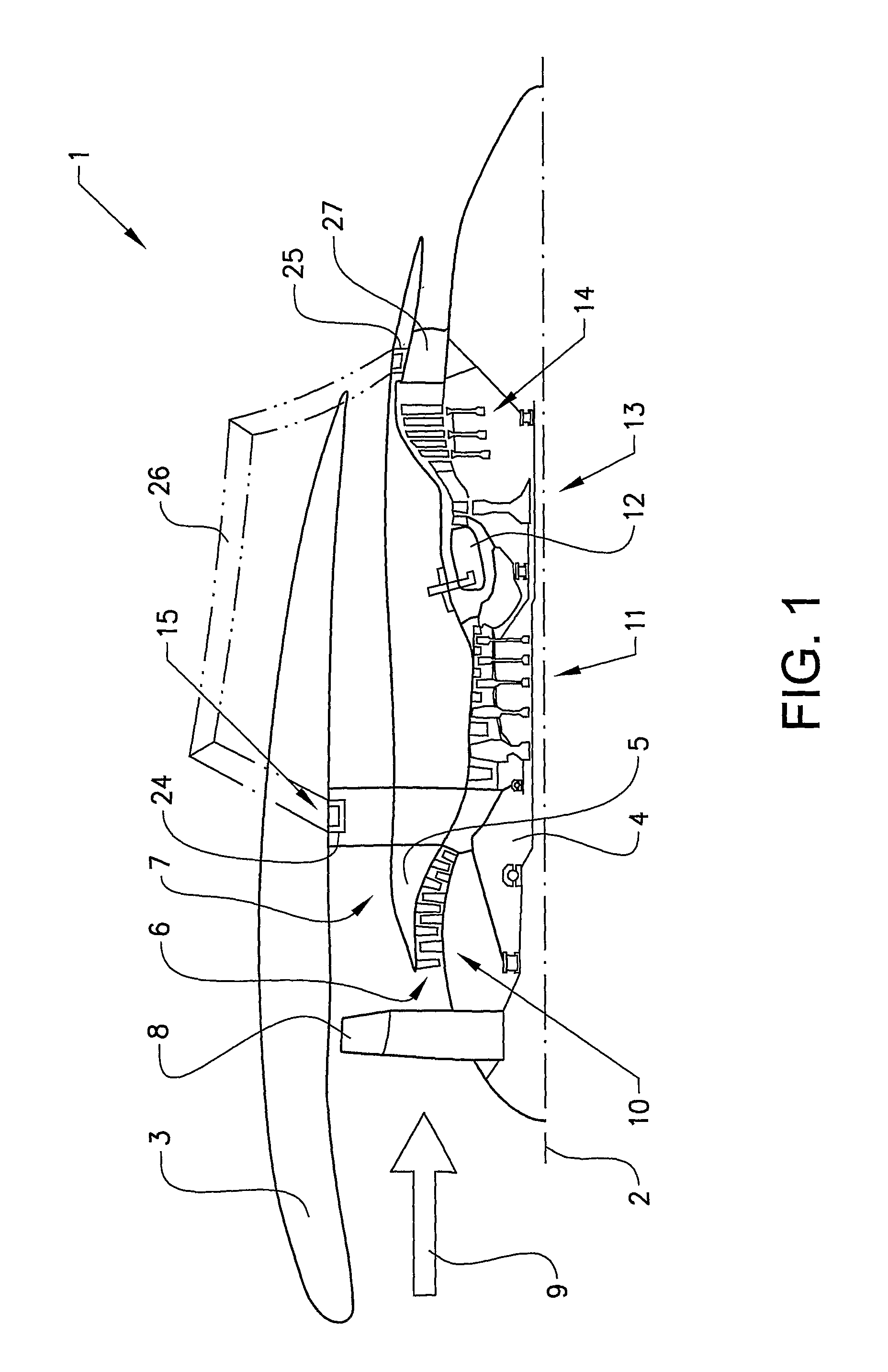
[0042]The invention will below be described for a turbofan gas turbine aircraft engine 1, which in FIG. 1 is circumscribed about an engine longitudinal central axis 2. The engine 1 comprises an outer casing 3, or nacelle, an inner casing 4, and an intermediate casing 5, which is concentric to the first two casings and divides the gap between them into an inner primary gas channel 6, or core duct, for the compression of air and a secondary channel 7 in which the engine bypass air flows. Thus, each of the gas channels 6, 7 is annular in a cross section perpendicular to the engine longitudinal central axis 2.

[0043]The engine 1 comprises a fan 8 which receives ambient air 9, a booster or low pressure compressor (LPC) 10 and a high pressure compressor (HPC) 11 arranged in the primary gas channel 6, a combustor 12 which mixes fuel with the air pressurized by the high pressure compressor 11 for generating combustion gases which flow downstream through a high pressure turbine (HPT) 13 and a...


PUM


Abstract

A strut for application between an outer ring and an inner ring in a gas turbine structure and a gas turbine structure including such a strut are provided. The strut includes an end portion which has a diverging shape so that an internal space is formed in the end portion for receiving at least part of an engine mount. Engine mounting lugs can be positioned at such struts.

Description

BACKGROUND AND SUMMARY[0001]The invention relates to a strut for application between an outer ring and an inner ring in a gas turbine structure. The invention also relates to a gas turbine structure comprising an outer ring, an inner ring and a plurality of circumferentially spaced struts extending between the inner ring and the outer ring.[0002]A gas turbine engine may be used as a jet engine. The term jet engine includes various types of engines, which admit air at relatively low velocity, heat it by combustion and shoot it out at a much higher velocity.[0003]Accommodated within the term jet engine are, for example, turbojet engines and turbo-fan engines. The invention will below be described for a turbo-fan engine, but may of course also be used for other engine types.[0004]An aircraft engine of the turbofan type generally comprises a forward fan and booster compressor, a middle core engine, and an aft low pressure power turbine. The core engine comprises a high pressure compress...

Claims


Application Information

Patent Timeline
Patent Type & Authority Patents(United States)
IPC IPC(8): F01D9/04F01D9/06F02C7/20
CPCF01D9/06F02C7/20F01D9/04Y02T50/671F01D5/145Y02T50/60
Inventor NILSSON, MARTINMARTENSSON, HANS
Owner GKN AEROSPACE SWEDEN AB
Learn More