Composite oxygen transport membrane

a technology of oxygen transport membrane and oxygen transport membrane, which is applied in the direction of pipes, preformed elements, inorganic chemistry, etc., can solve the problems of porous mass, and achieve the effect of reducing the cost involved, increasing the durability and life of the membran

Active Publication Date: 2014-08-05
PRAXAIR TECH INC
View PDF25 Cites 28 Cited by
  • Summary
  • Abstract
  • Description
  • Claims
  • Application Information

AI Technical Summary

Benefits of technology

[0010]As can be appreciated from the above discussion, since the composite membrane of the present invention is directly formed by sintering the layers in air, special sintering atmospheres do not have to be utilized. Furthermore, the porous layers do not use or is substantially free of pore formers. Both of these factors help to reduce the costs involved in fabricating such a composite membrane of the present invention. It is to be noted here that the production of a porous structure without the use of pore formers is a particularly unexpected result. In this regard, if (Ln1-xCax)wCr1-yByO3-δ is heated alone, it will sinter into a dense mass and will not be porous. The same will occur if a doped zirconia is sintered. However, if these materials are mixed together and then heated, a porous mass will result. Since such porous structure does not depend on pore formers and is formed at a temperature significantly higher than the membrane operation temperature during use, the pores will be less likely to close over time and therefore, the durability and life of the membrane will increase over prior art membranes. Furthermore, among other advantages of the present invention, Vanadium is not used and since all layers incorporate similar ABO3 materials, there will be a close thermal expansion match between layers.

Problems solved by technology

However, if these materials are mixed together and then heated, a porous mass will result.

Method used


Image

  • Composite oxygen transport membrane
  • Composite oxygen transport membrane

Examples


Embodiment Construction

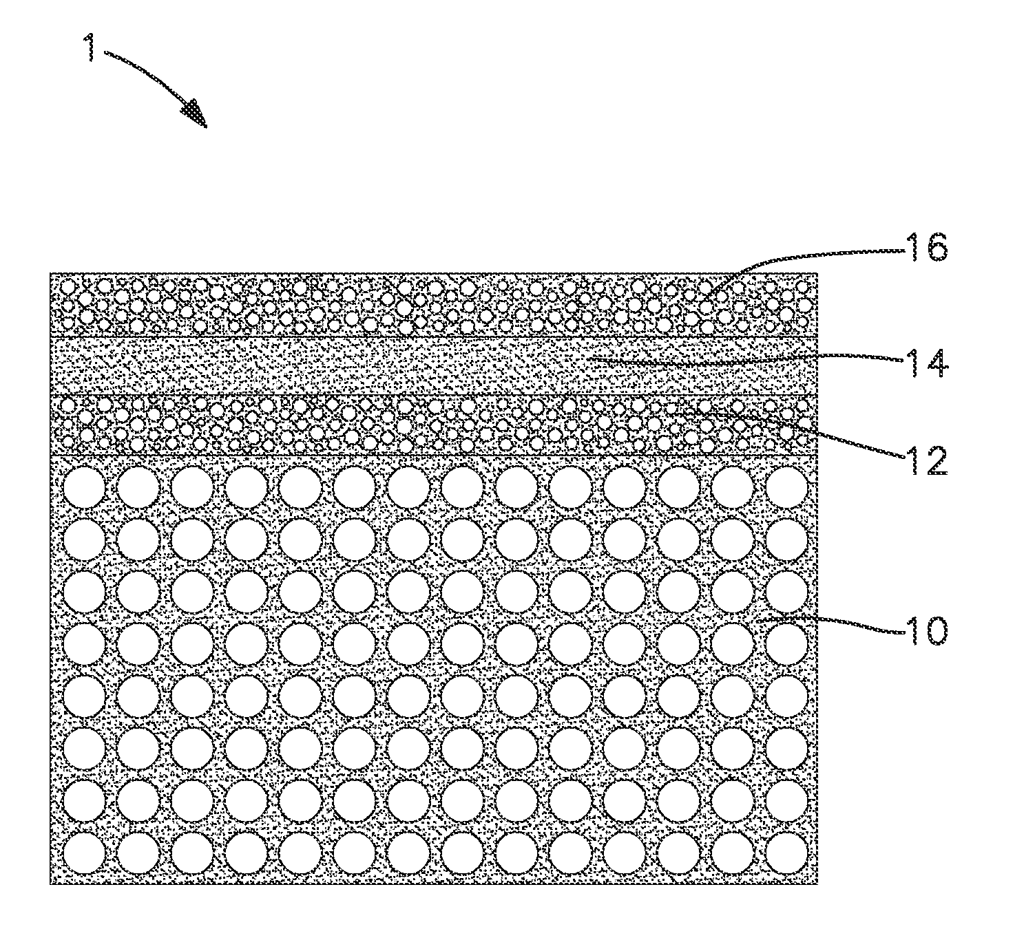
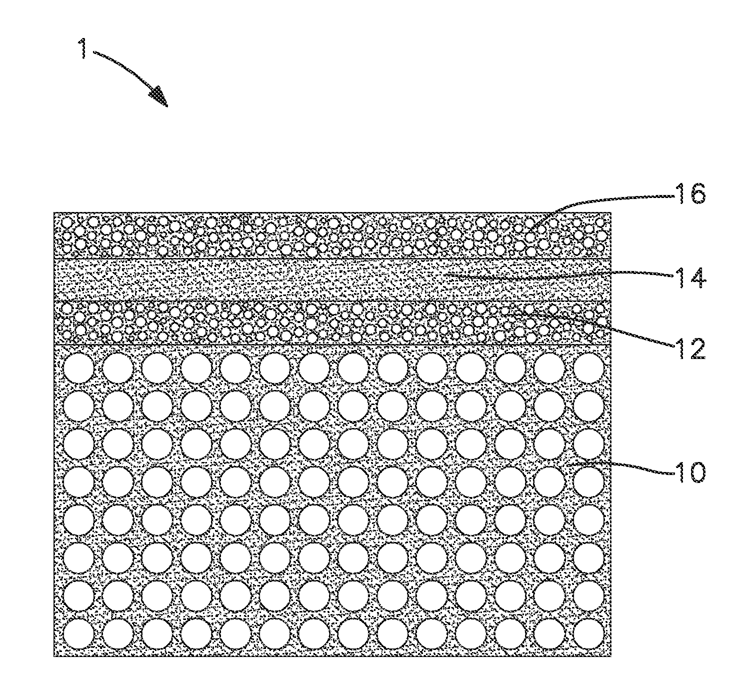
[0019]With reference to the FIGURE, a sectional, schematic view of a composite oxygen transport membrane 1 is illustrated. Composite oxygen transport membrane 1 has a porous support layer 10. Applied to the porous support layer 10 is a first layer 12, a second layer 14 and a third layer 16. The composite oxygen transport membrane is specifically designed to function in an environment in which a fuel or other combustible substance is introduced to the porous support layer 10, on the side opposite to the first, second and third layer 12, 14 and 16, and subjected to combustion supported by permeated oxygen to both provide the partial pressure difference necessary to drive oxygen ion transport and also to heat the membrane to an operational temperature at which oxygen ion transport will occur. As such, the first layer 12, which, as will be discussed, may optionally include a combustion catalyst, serves as a porous fuel oxidation layer at which combustion of the fuel or other combustible...


PUM

PropertyMeasurementUnit
volume ratioaaaaaaaaaa

Abstract

A method of producing a composite oxygen ion membrane and a composite oxygen ion membrane in which a porous fuel oxidation layer and a dense separation layer and optionally, a porous surface exchange layer are formed on a porous support from mixtures of (Ln1-xAx)wCr1-yByO3-δ and a doped zirconia. In the porous fuel oxidation layer and the optional porous surface exchange layer, A is Calcium and in the dense separation layer A is not Calcium and, preferably is Strontium. Preferred materials are (La0.8Ca0.2)0.95Cr0.5Mn0.5O3-δ for the porous fuel oxidation and optional porous surface exchange layers and (La0.8Sr0.2)0.95Cr0.5Fe0.5O3-δ for the dense separation layer. The use of such materials allows the membrane to sintered in air and without the use of pore formers to reduce membrane manufacturing costs. The use of materials, as described herein, for forming the porous layers have application for forming any type of porous structure, such as a catalyst support.

Description

CROSS REFERENCE TO RELATED APPLICATIONS[0001]The present application claims priority to and the benefit of U.S. provisional patent application Ser. No. 61 / 576,108 filed Dec. 15, 2011.[0002]This invention was made with Government support under Cooperative Agreement No. DE-FC26-07NT43088, awarded by the United States Department of Energy. The Government has certain rights in this invention.FIELD OF THE INVENTION[0003]The present invention relates to a method of forming a composite oxygen transport membrane and the composite oxygen transport membrane itself in which a porous fuel oxidation layer and a dense separation layer and optionally, a porous surface activation layer are formed on a porous support from mixtures of (Ln1-xAx)wCr1-yByO3-δ and a doped zirconia. More particularly, the present invention relates to such a method in which the porous fuel oxidation layer and the optional porous surface exchange layer are formed (La1-xCax)wCr1-yMnyO3-δ and the doped zirconia, the dense sep...

Claims


Application Information

Patent Timeline
Patent Type & Authority Patents(United States)
IPC IPC(8): B01D53/22
CPCB01D2257/104C04B2235/3262B01D71/028C01B13/0255C04B2235/3227C04B2111/00801C04B2235/3272B01D71/024C04B2235/3234C04B2111/0081C04B2235/3217B01D2256/12C04B2235/3243C04B35/2633C04B2235/3275C04B2235/3274C04B2235/3268C04B2235/3224C04B2235/3246C04B2235/3208B01D2325/023Y10T428/24999C04B2235/768Y10T428/24997C04B35/016B01D69/12B01D2255/402C04B2235/5445C04B2235/3222C04B2235/3225B01D2255/902Y10T428/1314B01D53/228C04B2235/3232C04B35/42C04B2111/00612C04B35/488C04B35/44C04B2235/3229C04B35/01C04B38/00B01D67/0041B01D2258/06C04B2235/80C04B35/462B01D2255/407B01D69/02C04B35/48C04B38/0074C04B35/443C04B35/04
Inventor CHRISTIE, GERVASE MAXWELLLANE, JONATHAN A.
Owner PRAXAIR TECH INC
Why Eureka
Try Eureka