
Exhaust gas purification catalyst

a purification catalyst and exhaust gas technology, applied in the field of exhaust gas purification catalysts, can solve the problems of low-temperature purification performance specific surface area decline, and low-temperature catalytic activity of catalysts post-durability testing still not satisfactory, so as to maintain purification performance and excellent purification performance.

Active Publication Date: 2014-08-05
TOYOTA JIDOSHA KK
View PDF45 Cites 11 Cited by
  • Summary
  • Abstract
  • Description
  • Claims
  • Application Information

AI Technical Summary

Benefits of technology

The invention introduces an exhaust gas purification catalyst that can maintain its performance even when exposed to high-temperature exhaust gas. The lower layer of the layer-structured catalyst coating layer (also known as the "Pd catalyst layer") is made of the ACZ composite oxide, which prevents crystal growth and maintains the support's durability and stable catalytic activity. The ACZ support's heat resistance is further increased by having a Ce / Zr atomic ratio ranging from 0.1-0.6. An alumina component content of 40-70 mass% in the ACZ composite oxide can further improve the catalyst's heat resistance and low-temperature activity.

Problems solved by technology

However, cerium oxide has a lower heat resistance than alumina, and when used at high temperatures, the crystalline structure changes and / or crystal growth advances, resulting in a decline in the specific surface area.
This is accompanied by a decline in the low-temperature purification performance of the catalyst post-durability testing.
However, the low-temperature catalytic activity of the catalyst post-durability testing has still not been satisfactory even using a CZ composite oxide.
In particular, after durability testing by exposure to high-temperature exhaust gas, these catalysts exhibit a substantial drop in catalytic activity from their initial level.
For a cerium oxide-containing support loaded with a noble metal catalyst, one cause of this substantial drop in catalytic activity is believed to be that the OSC of the catalyst after use in high-temperature durability testing exhibits a substantial decline from the OSC in initial use.
However, the previously described exhaust gas purification catalysts have not had a satisfactory low-temperature activity post-durability testing.

Method used


Image

  • Exhaust gas purification catalyst
  • Exhaust gas purification catalyst
  • Exhaust gas purification catalyst

Examples


production examples

Comparative Examples 1 to 3

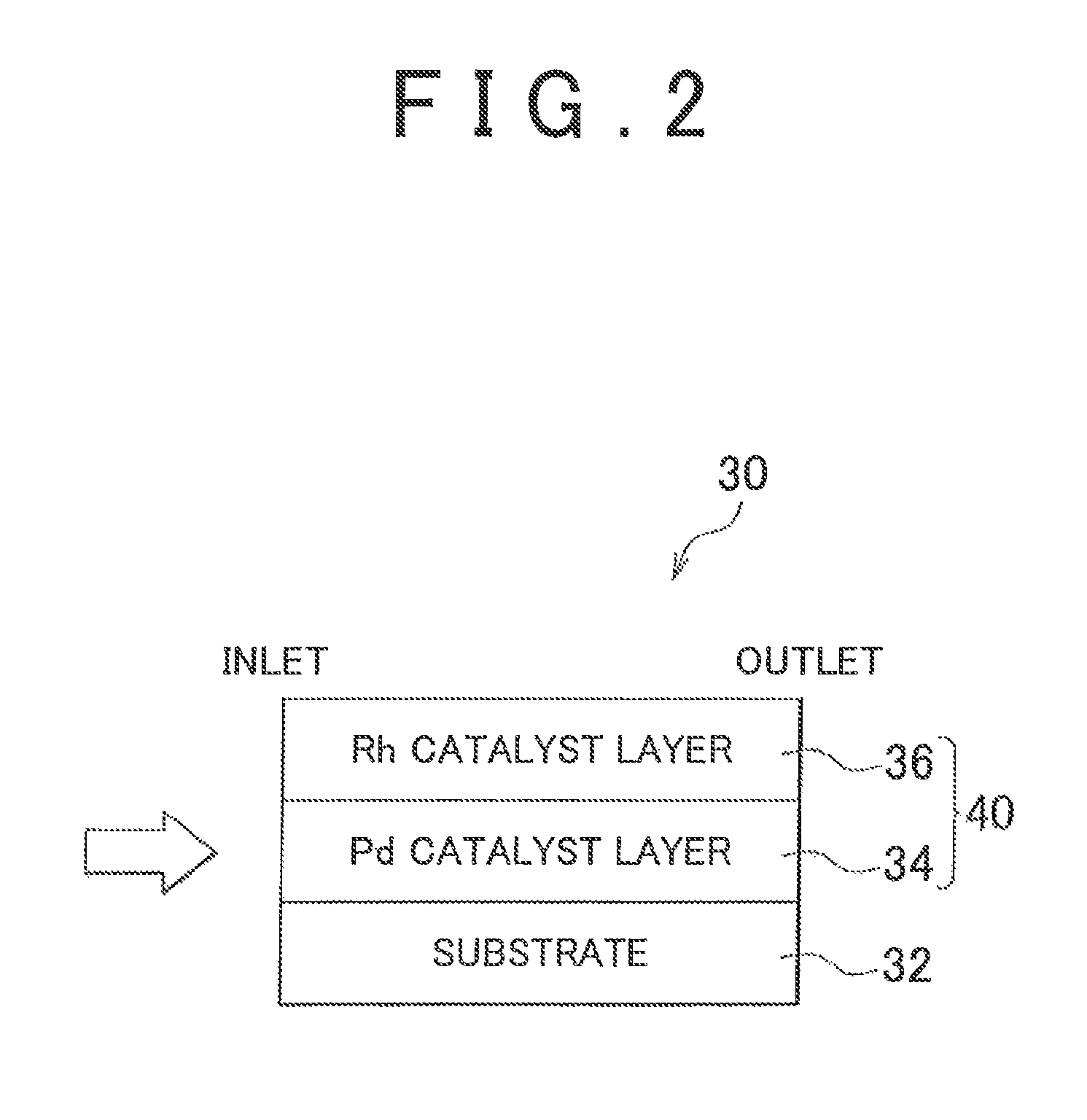
[0056]For Comparative Example 1, a catalyst was prepared using an Al—Zr composite oxide (AZ composite oxide) made of Al2O3 and ZrO2 for the lower catalyst coating layer (Pd catalyst layer) 34 rather than the ACZ composite oxide. The AZ composite oxide was prepared by the same production process as the previously described production process for the ACZ composite oxides of Examples 1 to 6, but in this case not including the cerium nitrate in the starting materials. Letting the AZ composite oxide be 100 mass %, the component proportions for the Al and Zr in the AZ composite oxide had been brought to 50.65 mass % for the Al2O3 content and 45.31 mass % for the ZrO2. The cerium-to-zirconium atomic ratio (Ce / Zr) in the lower layer support in this case was of course 0 (Table 1).

[0057]For Comparative Example 2, a catalyst was prepared using a CZ composite oxide for the support for the lower catalyst coating layer (Pd catalyst layer) 34 in place of the ACZ composit...


PUM

PropertyMeasurementUnit
specific surface areaaaaaaaaaaa
particle diameteraaaaaaaaaa
temperatureaaaaaaaaaa

Abstract

An exhaust gas purification catalyst is provided with a catalyst coating layer (40) formed on the surface of a substrate (32). This catalyst coating layer (40) is formed of an upper catalyst coating layer (36) in which Rh particles are supported on a porous support, and a lower catalyst coating layer (34) in which Pd particles are supported on a support that contains an ACZ composite oxide made of alumina (Al2O3), ceria (CeO2), and zirconia (ZrO2).

Description

CROSS-REFERENCE TO RELATED APPLICATIONS[0001]This application is a national phase application of International Application No. PCT / IB2012 / 000386, filed Mar. 2, 2012, and claims the priority of Japanese Application No. 2011-053404, filed Mar. 10, 2011, the content of both of which is incorporated herein by reference.BACKGROUND OF THE INVENTION[0002]1. Field of the Invention[0003]The invention relates to an exhaust gas purification catalyst, and more particularly relates to a ceramic support that is a constituent of this catalyst.[0004]2. Description of Related Art[0005]Three-way catalysts are widely used as catalysts for the purification of the hydrocarbon (HC), carbon monoxide (CO), and nitrogen oxides (NOx) present in the exhaust gas emitted from engines in, e.g., automobiles and so forth. In a typical three-way catalyst structure, for example, an alumina coating layer is formed on the surface of a highly heat-resistant ceramic substrate and platinum (Pt), palladium (Pd), and rhodi...

Claims


Application Information

Patent Timeline
Patent Type & Authority Patents(United States)
IPC IPC(8): B01J20/00B01J21/00B01J21/04B01J23/00B01J23/08B01J23/40B01J23/42B01J23/44B01J23/56
CPCB01J23/63B01D53/945B01D2255/1023B01D2255/1025B01D2255/2065B01D2255/20715B01D2255/2092B01D2255/407B01D2255/9022B01D2255/908B01D2255/9207B01D2258/014B01J23/002B01J35/0006B01J35/04B01J35/1014B01J35/1061B01J37/0244B01J37/0248Y02T10/22Y02T10/12B01J35/19B01J35/56B01J35/613B01J35/647
Inventor CHINZEI, ISAO
Owner TOYOTA JIDOSHA KK
Learn More