Semiconductor device including switch electrically connected to signal line

a technology of a switch and a signal line, which is applied in the direction of semiconductor/solid-state device details, pulse techniques, instruments, etc., can solve the problems of complex driver circuit, difficult for transistor including amorphous silicon to drive at high frequencies, and difficult for transistor including single crystal silicon or polycrystalline silicon to be formed by a low-temperature process

Active Publication Date: 2014-08-05
SEMICON ENERGY LAB CO LTD
View PDF131 Cites 2 Cited by
  • Summary
  • Abstract
  • Description
  • Claims
  • Application Information

AI Technical Summary

Benefits of technology

[0016]In a semiconductor device which is an embodiment of the present invention, a distance between two adjacent signal lines which go into a floating state in different periods is longer than a distance between two adjacent signal lines which go into a floating state in the same period. Consequently, variation in potential of a signal line due to capacitive coupling can be suppressed. For example, in the case where the signal line is a source signal line in an active matrix display device, formation of a stripe pattern in a displayed image can be suppressed.

Problems solved by technology

However, it is difficult for the transistor including amorphous silicon to be driven at high frequencies, and it is difficult for the transistor including single crystal silicon or polycrystalline silicon to be formed by a low-temperature process.
However, in the case of performing data division driving, a driver circuit has a complex structure; for example, the number of wirings which supply image signals to a pixel portion (hereinafter, such wirings are also referred to as data signal lines) is increased.

Method used


Image

  • Semiconductor device including switch electrically connected to signal line
  • Semiconductor device including switch electrically connected to signal line
  • Semiconductor device including switch electrically connected to signal line

Examples


embodiment 1

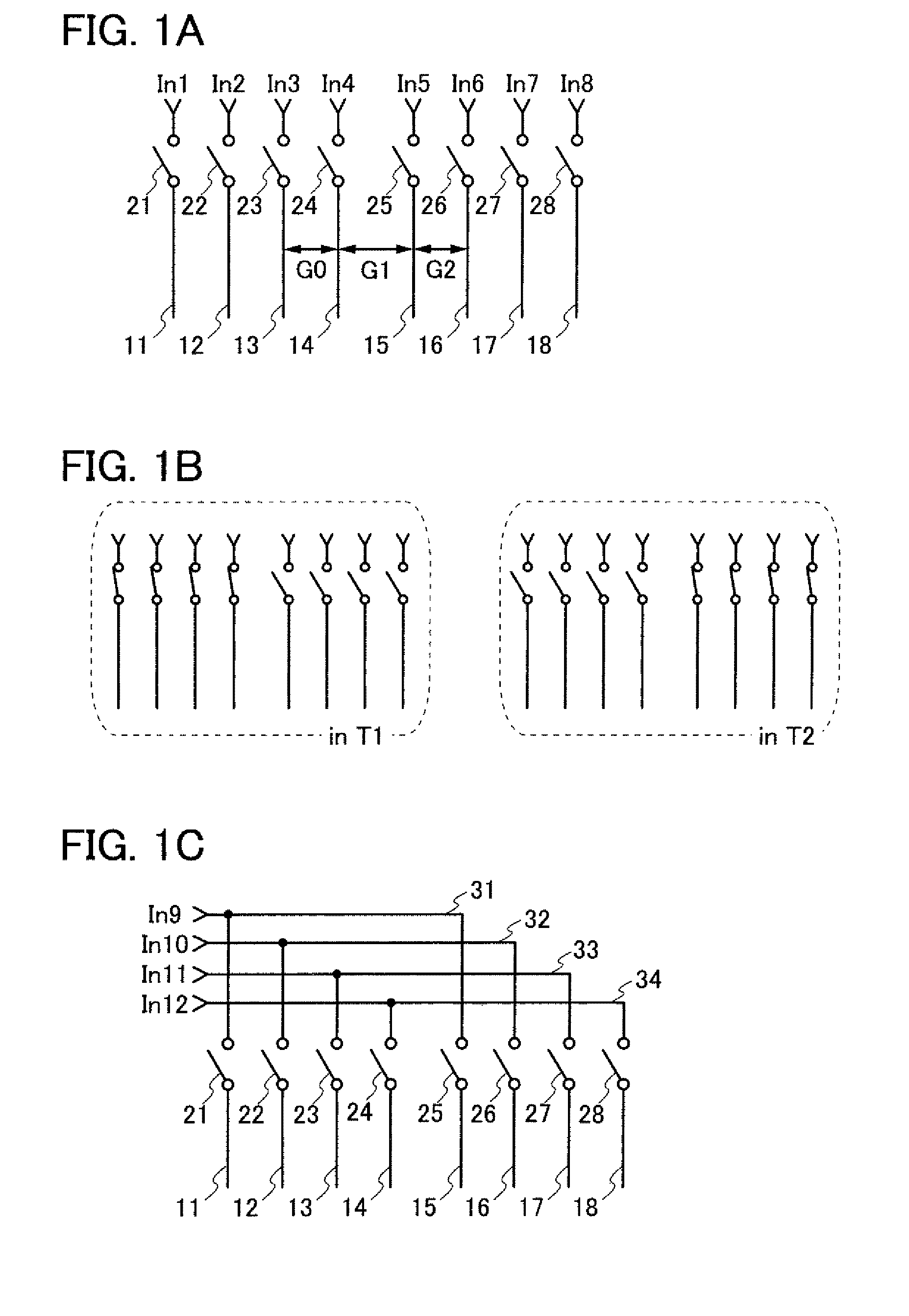
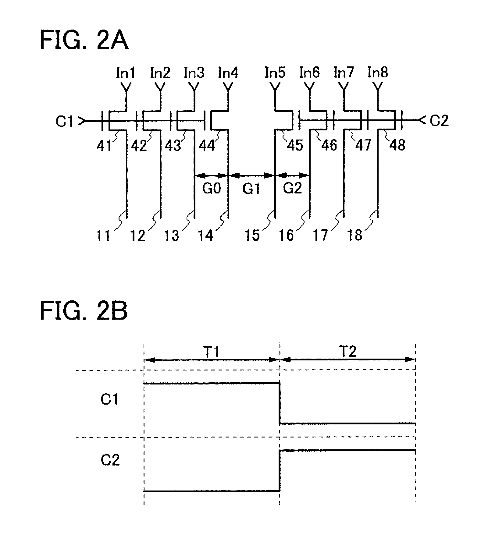
[0033]In this embodiment, a semiconductor device which is an embodiment of the present invention is described with reference to FIGS. 1A to 1C, FIGS. 2A and 2B, FIGS. 3A and 3B, FIGS. 4A to 4C, FIGS. 5A and 5B, FIGS. 6A and 6B, and FIG. 7.

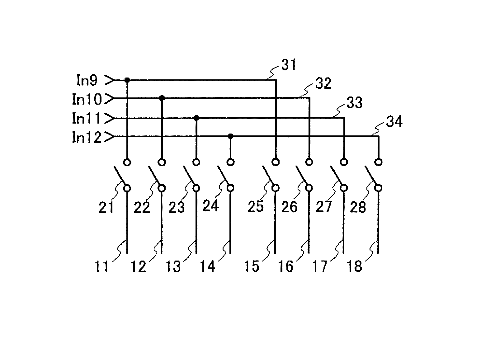
[0034]FIG. 1A illustrates positions of a plurality of signal lines 11 to 18 and a plurality of switches 21 to 28 which control input of a signal to the plurality of signal lines 11 to 18, which are included in a semiconductor device of this embodiment. Note that the switch 21 controls supply of an input signal (In1) to the signal line 11. Similarly, the switches 22 to 28 control supply of input signals (In2 to In8) to the signal lines 12 to 18. In addition, the plurality of signal lines 11 to 18 are arranged parallel or approximately parallel to one another. Further, a distance between the signal line 14 and the signal line 15 (G1) is longer than a distance between the signal line 13 and the signal line 14 (G0) and longer than a distance between th...

embodiment 2

[0057]In this embodiment, a semiconductor device of an embodiment of the present invention is described. Specifically, an example of an active matrix display device which performs data division driving is described with reference to FIGS. 8A and 8B, FIGS. 9A and 9B, FIG. 10, FIG. 11, and FIG. 12.

[0058]FIG. 8A illustrates a structure example of an active matrix display device. A display device illustrated in FIG. 8A includes a pixel portion 101, a source signal line driver circuit 102, a gate signal line driver circuit 103, a plurality of source signal lines 104 which are arranged in parallel or approximately parallel, and a plurality of gate signal lines 105 which are arranged in parallel or approximately parallel. The pixel portion 101 includes a plurality of pixels 107. Note that the plurality of pixels 107 are arranged in matrix. Each of the plurality of source signal lines 104 is electrically connected to pixels in any column of the plurality of pixels arranged in matrix, and ea...

embodiment 3

[0083]In this embodiment, an example of a transistor included in the semiconductor device described in Embodiment 1 or Embodiment 2 will be described. Specifically, examples of a structure of a transistor whose channel formation region is formed using an oxide semiconductor and a method for manufacturing the transistor are described with reference to FIGS. 13A to 13D.

[0084]FIGS. 13A to 13D illustrate examples of a specific structure and a process for manufacturing the transistor in Embodiment 1. Note that a transistor 410 illustrated in FIG. 13D has a bottom-gate structure called a channel-etched type and is also referred to as an inverted-staggered transistor. Although a single-gate transistor is illustrated in FIG. 13D, a multi-gate transistor including a plurality of channel formation regions can be formed as needed.

[0085]A process for manufacturing the transistor 410 over a substrate 400 is described below with reference to FIGS. 13A to 13D.

[0086]First, a conductive film is form...


PUM


Abstract

To suppress variation of a signal in a semiconductor device. By suppressing the variation, formation of a stripe pattern in displaying an image on a semiconductor device can be suppressed, for example. A distance between two adjacent signal lines which go into a floating state in different periods (G1) is longer than a distance between two adjacent signal lines which go into a floating state in the same period (G0, G2). Consequently, variation in potential of a signal line due to capacitive coupling can be suppressed. For example, in the case where the signal line is a source signal line in an active matrix display device, formation of a stripe pattern in a displayed image can be suppressed.

Description

TECHNICAL FIELD[0001]The present invention relates to a semiconductor device. In particular, the present invention relates to a semiconductor device which displays an image by active matrix driving. Further, the present invention relates to an electronic device including the semiconductor device.[0002]Note that the semiconductor device in this specification indicates all the devices that operate by utilizing semiconductor characteristics.BACKGROUND ART[0003]A semiconductor device which displays an image by active matrix driving (hereinafter such a device is also referred to as an active matrix display device) has been widely used. The semiconductor device includes a pixel portion in which an image is displayed and a driver circuit which controls displaying of an image in the pixel portion. Specifically, in the semiconductor device, an image signal input to a plurality of pixels arranged in matrix in the pixel portion is controlled by the driver circuit and an image is thus displayed...

Claims


Application Information

Patent Timeline
Patent Type & Authority Patents(United States)
IPC IPC(8): H01L31/119H01L33/00H01L27/10H01L31/036H01L29/94H01L29/04H01L31/113H01L29/76H01L31/062
CPCG02F1/13454G02F2001/136295G09G2300/0426G09G2320/0209G09G3/3688G09G2300/0408H01L27/1225G02F2001/13685H01L27/124G02F1/136286G02F1/133305G02F1/136295G02F1/13685
Inventor SHISHIDO, HIDEAKI
Owner SEMICON ENERGY LAB CO LTD
Why Eureka
Try Eureka