End-pumped alignment and temperature insensitive laser target designator and marker

a laser target and temperature-sensitive technology, applied in the direction of laser details, optical resonator shape and construction, active medium shape and construction, etc., can solve the problems of reducing the effectiveness of laser target designators, reducing the cost of materials and assembly, and not being able to use porro prisms as the terminators of both ends of resonator paths, etc., to achieve low manufacturing cost and high beam quality

Active Publication Date: 2014-08-05
BAE SYST INFORMATION & ELECTRONICS SYST INTERGRATION INC
View PDF12 Cites 2 Cited by
  • Summary
  • Abstract
  • Description
  • Claims
  • Application Information

AI Technical Summary

Benefits of technology

[0013]A laser target designator includes a novel optical resonator design that uses a total internal reflection “bounce” geometry to place an end-pumped gain element functionally in the center of the resonator path, thereby allowing the resonator path to be terminated at both ends by a pair of Porro prisms and providing a high beam quality design that is insensitive to temperature and to alignment, compact, light in weight, and low in manufacturing cost. Embodiments use the same gain medium as an oscillator gain medium and an amplifier gain medium.
[0015]By using this bounce geometry to place the gain element in the center of the optical resonator, the present design allows both ends of the resonator to be terminated by crossed Porro prisms, thereby providing the insensitivity to alignment and to temperature typically achieved by conventional designs that use side-pumped gain elements (see FIG. 1), but with greatly reduced bulk and weight. Due to this alignment insensitivity, embodiments of the invention incorporate block optics in a planar layout that provides a suitable platform for automated assembly on a standard support media such as aluminum.
[0016]The bounce geometry of the present invention also limits the effective aperture of the gain element, thereby reducing beam divergence and improving the quality of the beam. The improved beam quality allows the transmit optic diameter to be minimized, thereby reducing the power required to achieve a desired target brightness, and further reducing the weight and size of the designator.
[0017]In addition, the internal reflectance of the light within the gain element causes the light to traverse an increased path length within the gain element. This allows the oscillator to be operated using a smaller mode volume to generate a high brightness beam, thereby providing gain that would be typical of a much longer gain element that did not use a bounce geometry. As a result, the physical length of the gain element, and of the designator as a whole, is further reduced.
[0018]Certain embodiments of the present invention use a single gain element as both an oscillator gain element and an amplifier gain element. In some of these embodiments, the oscillator beam undergoes total internal reflection within the gain medium, while the extracted output beam passes twice more through the same gain medium without internal reflection, thereby maximizing the use of the gain element volume for increased laser energy without degrading the fundamental oscillator beam quality or efficiency.

Problems solved by technology

Unfortunately, currently deployed laser designating systems such as the design illustrated in FIG. 1 tend to be heavy and bulky, and require assembly in the field, thereby reducing their effectiveness, especially for dismounted observers.
However, since the highly reflective mirror 204 is deposited on the gain element 100 at one end of the resonator path, it is not possible to use a pair of Porro prisms as the terminators of both ends of the resonator path.
However, this approach significantly increases the cost of materials and of assembly.
In addition, even if the internal temperature of the designator is regulated, the use of an optical-quality rail 200 does not compensate for thermal lensing of the gain medium 100 and the resulting mirror misalignments due to variations in average output power due to differing pulse rate codes.

Method used


Image

  • End-pumped alignment and temperature insensitive laser target designator and marker
  • End-pumped alignment and temperature insensitive laser target designator and marker
  • End-pumped alignment and temperature insensitive laser target designator and marker

Examples


Embodiment Construction

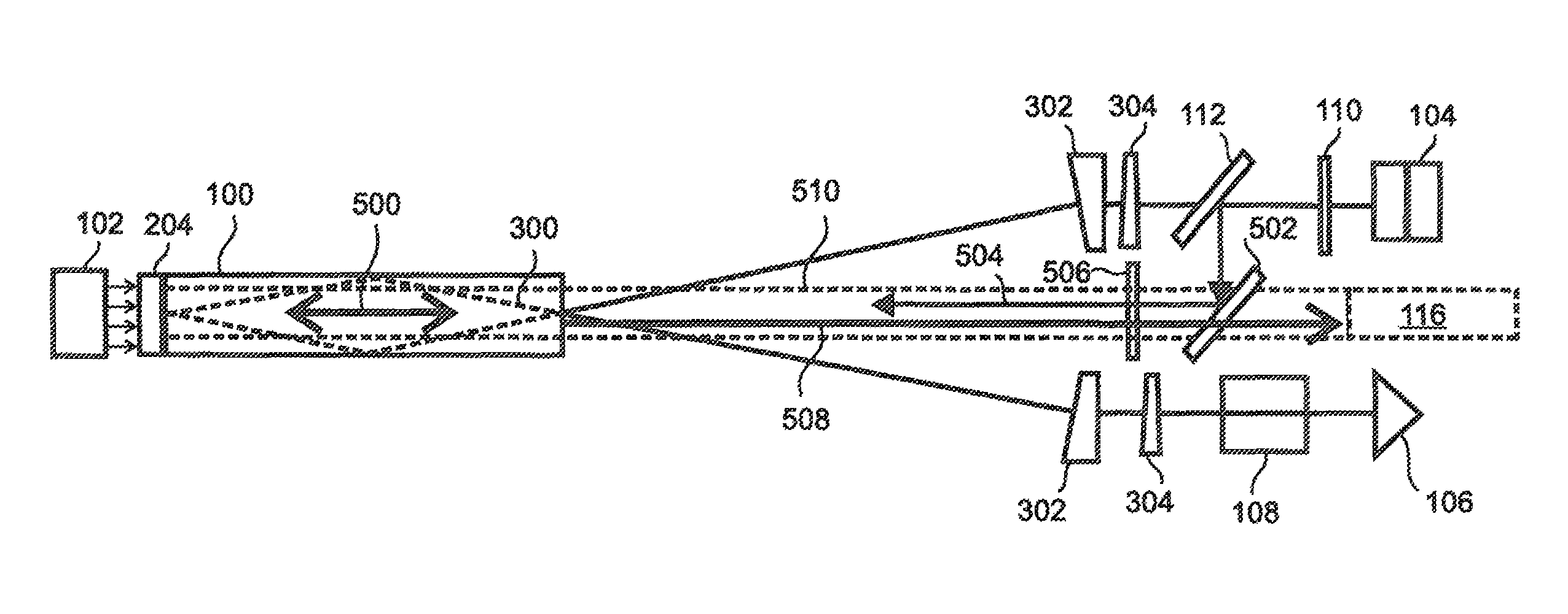
[0037]With reference to FIG. 3, the present invention is a laser target designator having a novel optical resonator design that uses a bounce geometry to place an end-pumped gain element 100 functionally in the center of the resonator, thereby allowing the resonator to be terminated by a pair of Porro prisms 104, 106 and providing a high beam quality design that is insensitive to temperature, insensitive to alignment, compact, light in weight, and low in manufacturing cost.

[0038]As can be seen in FIG. 3, the light within the resonator 300 enters the gain element 100 at an angle and undergoes total internal reflection or “TIR.” Herein this TIR configuration is referred to as a “bounce” geometry. After undergoing TIR, the oscillator light emerges from the gain element 100 at a symmetrically opposite angle.

[0039]This bounce geometry requires that the beam be reflected back to the gain element 100 from two locations, and thereby functionally places the gain element 100 at the center of ...


PUM


Abstract

A compact, lightweight, laser target designator uses a TIR bounce geometry to place an end-pumped gain element functionally in the center of the resonator path, thereby allowing the resonator path to be terminated by a pair of crossed Porro prisms, so that the designator produces a high quality beam that is insensitive to alignment and temperature, and is low in manufacturing cost. Some embodiments fold the Porro legs of the resonator path back toward the gain element for compactness. Embodiments use a single gain element as both an oscillator gain element with TIR and as an output amplifier gain element without TIR. Various embodiments use block optical elements in a planar layout on a standard support medium such as aluminum to facilitate automated manufacturing.

Description

RELATED APPLICATIONS[0001]This application is a national phase application filed under 35 USC §371 of PCT application PCT / US2012 / 047095, filed on Jul. 18, 2012, which claims the benefit of U.S. Provisional Application No. 61 / 527,232, filed Aug. 25, 2011. Both applications are which is herein incorporated by reference in their entirety for all purposes.FIELD OF THE INVENTION[0002]The invention relates to laser target designators, and more particularly, to laser target designators that incorporate end-pumped gain media.BACKGROUND OF THE INVENTION[0003]A laser designator is a laser light source which is used to designate a military target. Laser designators provide targeting for laser guided bombs, missiles, and precision artillery munitions. The designator is used to apply laser light to the target, causing the light to bounce off the target into the sky, where it is detected by the seeker on a laser guided munition, which steers itself towards the source of the reflected light.[0004]...

Claims


Application Information

Patent Timeline
Patent Type & Authority Patents(United States)
IPC IPC(8): H01S3/11H01S3/06H01S3/08H01S3/081H01S3/0941
CPCH01S3/11H01S3/09415H01S3/08059H01S3/08095H01S3/0816H01S3/0621H01S5/423H01S3/1123
Inventor MCCARTHY, JOHN C.SNELL, KATHERINE J.MILLER, CHRISTOPHER A.
Owner BAE SYST INFORMATION & ELECTRONICS SYST INTERGRATION INC
Why Eureka
Try Eureka