Laser projector for removing speckle noise

a laser projector and speckle noise technology, applied in the field of projectors, can solve the problems of short life, limited reproducing range, low light use efficiency, etc., and achieve the effect of removing speckle nois

Inactive Publication Date: 2014-08-19
PANASONIC CORP
View PDF13 Cites 4 Cited by
  • Summary
  • Abstract
  • Description
  • Claims
  • Application Information

AI Technical Summary

Benefits of technology

[0014]In view of the above, it is an object of the present invention to provide a laser projector that enables to sufficiently remove speckle noise, and display high-grade images, using a laser light source, and a two-dimensional light modulator.
[0016]The above arrangement enables to sufficiently remove speckle noise, and display high-grade images, using the laser light source, and the two-dimensional light modulator.

Problems solved by technology

However, the lamp light source has drawbacks that the life is short, the color reproducing range is limited, the volume of the light source is large, and the light use efficiency is low.
In a projector (hereinafter, called as a laser projector) incorporated with a laser light source, however, speckle noise resulting from high coherence of laser light has become a problem.
The speckle noise obstructs the viewer from viewing an image on a screen, and causes serious image degradation.
However, since the above proposals are made considering speckle noise reduction in a lamp light source, an angle change amount is small, and a sufficient speckle noise removal effect is not obtained, if the above proposals are applied to a laser light source.
Patent literature 3, however, may fail to remove speckle noise under a condition including a case that image projection is performed in a state that a portable projector is fixed.
However, none of the proposals provides a sufficient speckle noise removal effect in a laser projector, and the proposals fail to remove speckle noise, utilizing a two-dimensional light modulator.

Method used


Image

  • Laser projector for removing speckle noise
  • Laser projector for removing speckle noise
  • Laser projector for removing speckle noise

Examples


first embodiment

[0029](First Embodiment)

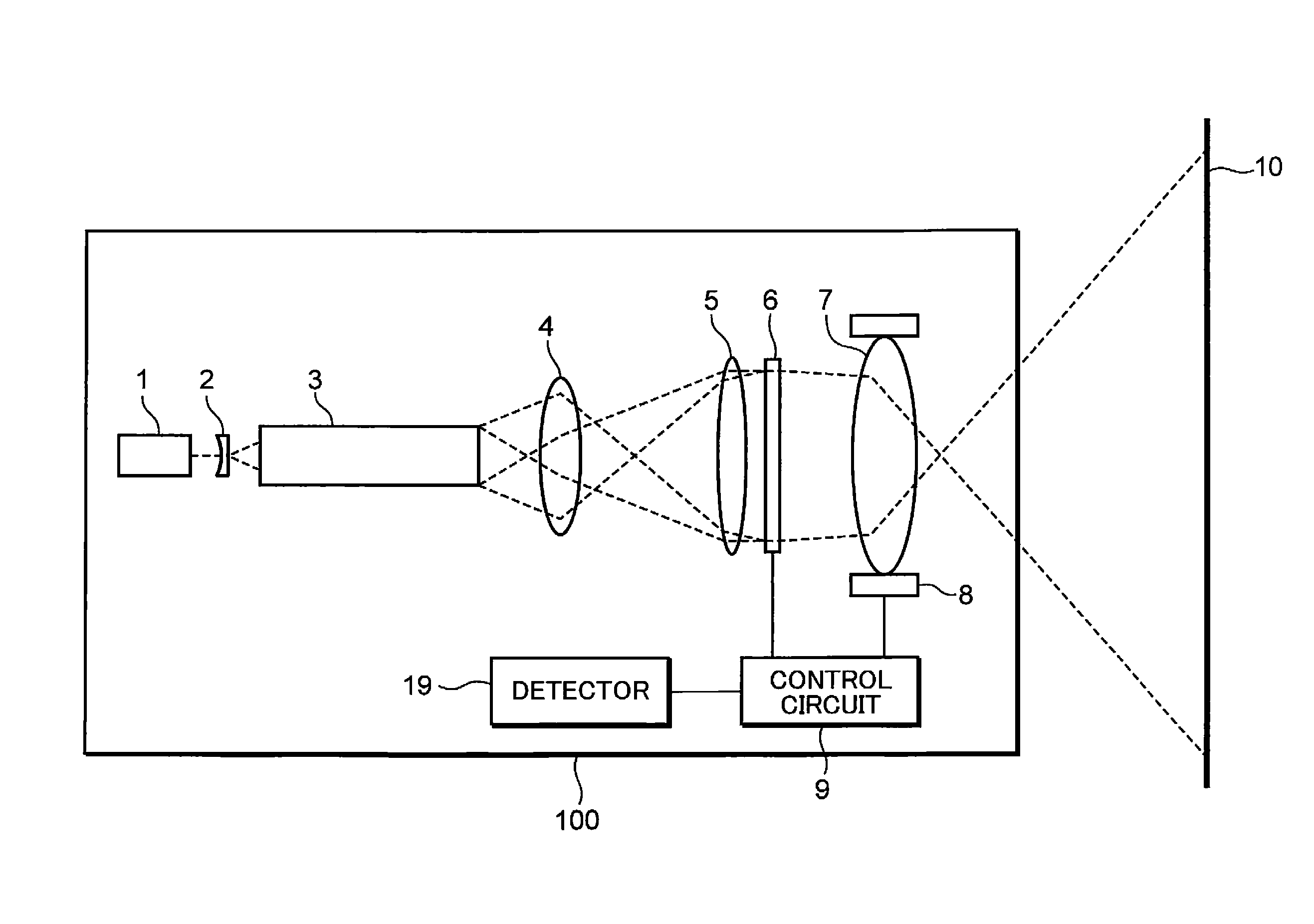
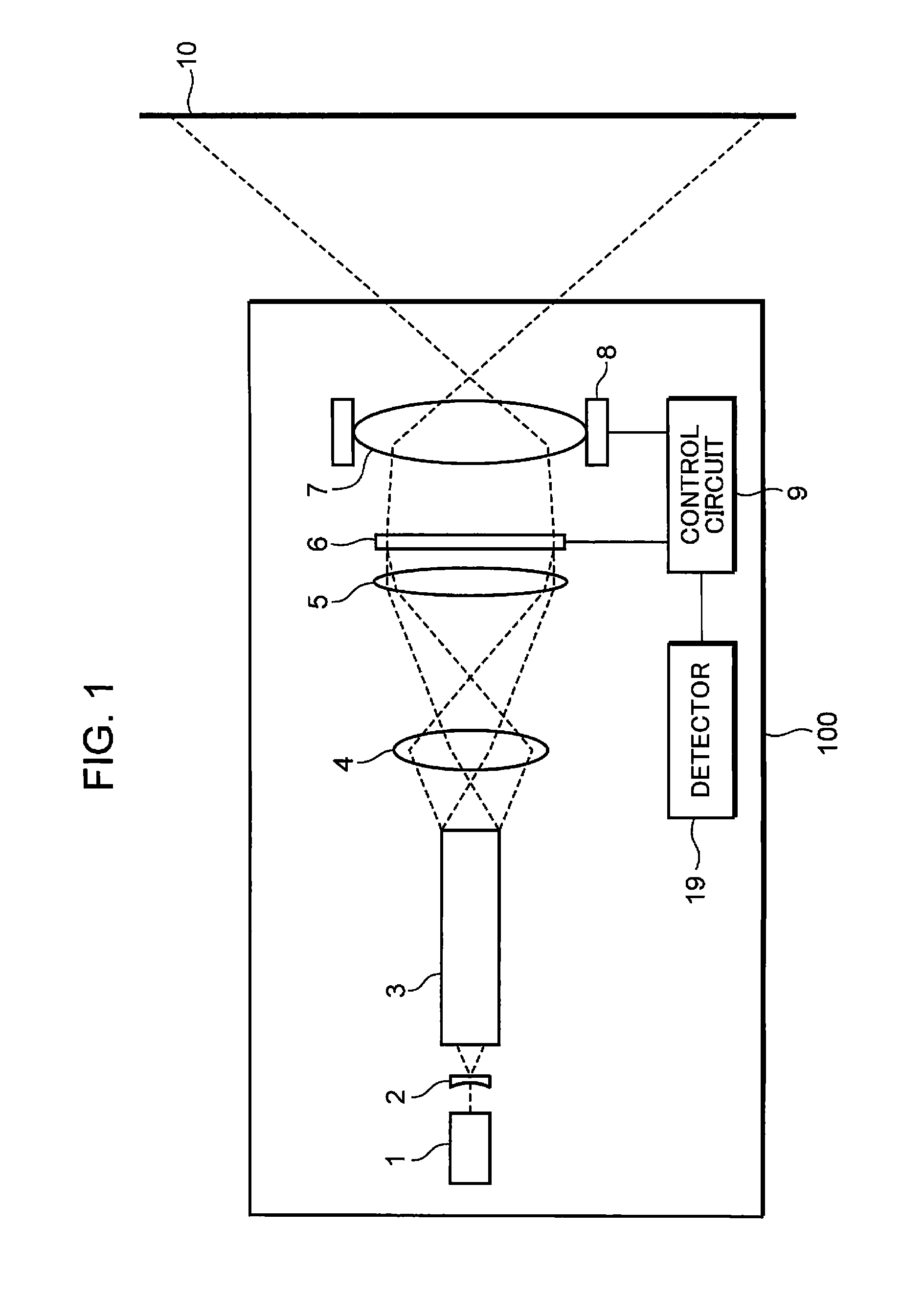
[0030]FIG. 1 is a schematic construction diagram of a laser projector 100 in the first embodiment of the invention. The laser projector 100 shown in FIG. 1 includes a laser light source 1, a lens 2, a rod integrator 3, a relay lens 4, a field lens 5, a two-dimensional light modulator 6, a projection optical system 7, a driver 8, and a control circuit 9.

[0031]Laser light emitted from the laser light source 1 is transmitted through the lens 2, subjected to beam shaping by the rod integrator 3, transmitted through the relay lens 4 and the field lens 5, and illuminates the two-dimensional light modulator 6. The two-dimensional light modulator 6 modulates the laser light in accordance with a video signal (a display signal) from the control circuit 9 to form an image. The projection optical system 7 enlarges and projects the image formed by the two-dimensional light modulator 6 on a display plane 10. In response to receiving a video signal from an external device, ...

second embodiment

[0051](Second Embodiment)

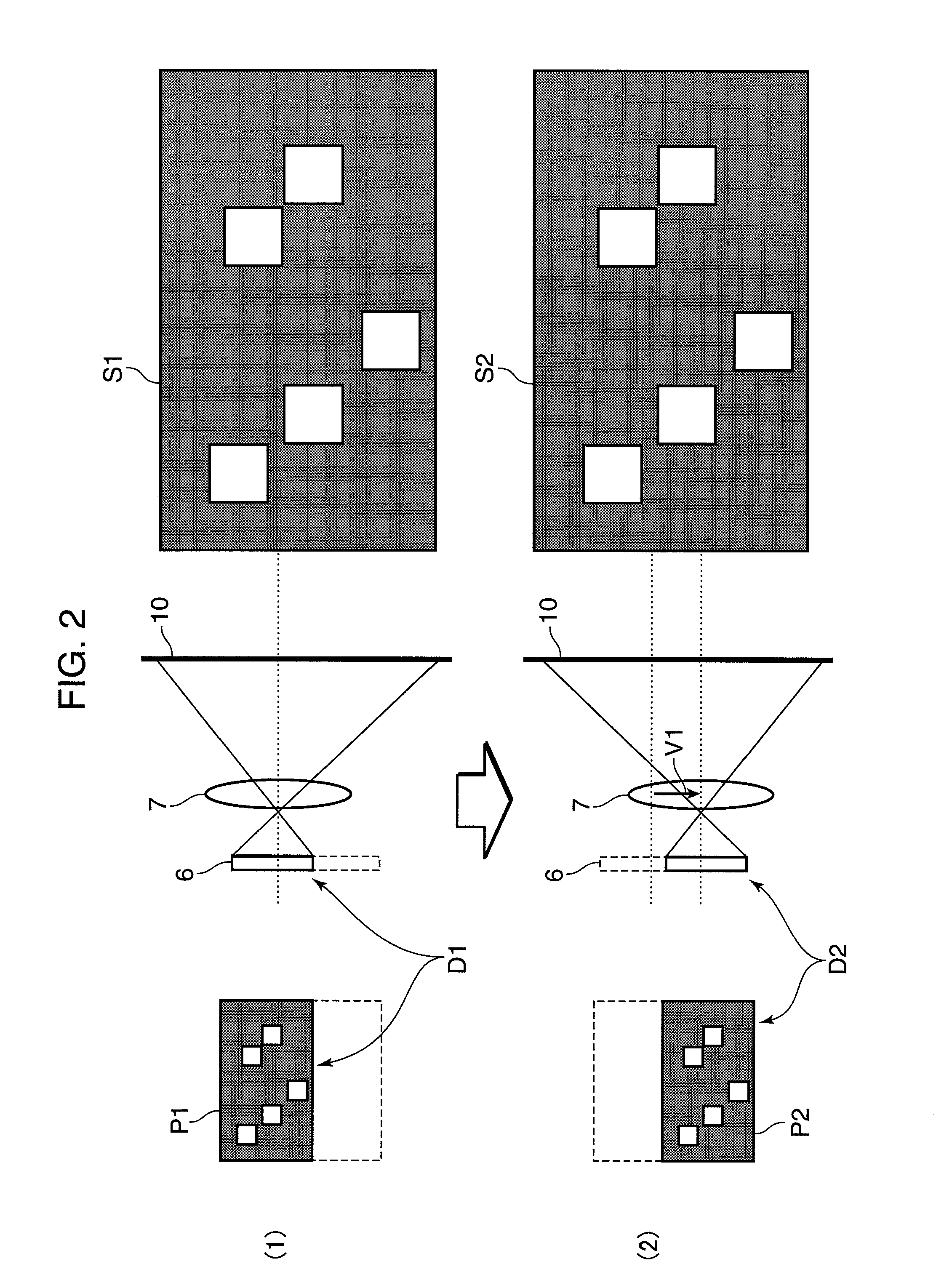
[0052]FIG. 3 is a schematic construction diagram of a laser projector 101 in the second embodiment, and shows a state that an illumination region of laser light is shifted in synchronism with shift of a display position D1, D2 of a two-dimensional light modulator 6 in the laser projector 101. In the section (2) of FIG. 3, to simplify the illustration, a driver 8 for a projection optical system 7, a driver 42 for a relay lens 41, and a control circuit 90 for controlling the drivers 8 and 42, and the two-dimensional light modulator 6 shown in the section (1) of FIG. 3 are not illustrated.

[0053]The second embodiment is different from the first embodiment in a point that the illumination region with respect to the two-dimensional light modulator 6 is also shifted in performing the display operation as shown in the sections (1) and (2) of FIG. 2. The shift operation of the illumination region is illustrated in FIG. 3. Specifically, the relay lens 41 is supported ...

third and fourth embodiments

[0065](Third and Fourth Embodiments)

[0066]A laser light source such as a semiconductor laser, a solid-state laser, or a wavelength conversion laser may be used as a laser light source in the invention. The laser projector 100 shown in FIG. 1 is an example of using a single laser light source. In the case where a color image is displayed by using three colors of R, G and B, laser light sources for emitting laser light of three colors of R, G, and B may be used. A color laser projector 200 in the third embodiment shown in FIG. 4, and a color laser projector 300 in the fourth embodiment shown in FIG. 5 are construction examples using laser light sources for emitting laser light of three colors of R, G, and B. The number of laser light sources is not specifically limited, and laser light sources for emitting laser light of four or more colors may be used.

[0067]FIG. 4 is a schematic construction diagram of the color laser projector 200 in the third embodiment of the invention. In FIG. 4,...


PUM


Abstract

A laser projector includes a laser light source; a two-dimensional light modulator which modulates light from the laser light source; and a projection optical system which projects images onto a display plane by expanding the light modulated by the two-dimensional light modulator. Shift of a display position of the two-dimensional light modulation element and shift of the projection optical system are performed in synchronization with each other so that display positions of the images on the display plane are made substantially identical to each other. Thereby, speckle noise is sufficiently removed, and high-grade images are displayed.

Description

BACKGROUND OF THE INVENTION[0001]1. Technical Field[0002]The present invention relates to a projector incorporated with a laser light source as a light source.[0003]2. Background Art[0004]A projector for displaying an image on a screen has been spread as an image display device. Generally, a lamp light source is used in the projector. However, the lamp light source has drawbacks that the life is short, the color reproducing range is limited, the volume of the light source is large, and the light use efficiency is low.[0005]A laser light source has been attempted to be used as a light source in a projector to solve the above drawbacks. Since the laser light source has a long life and a strong directionality, as compared with a lamp light source, the light use efficiency of the laser light source can be easily enhanced. Further, since the laser light source has monochromaticity, the laser light source has a wide color reproducing range, and is capable of displaying a clear image. Furt...

Claims


Application Information

Patent Timeline
Patent Type & Authority Patents(United States)
IPC IPC(8): G03B21/00G02B26/08G02B27/09G02B27/48G03B3/00G03B21/14H04N9/31
CPCG03B21/00H04N9/317H04N9/3161H04N9/3102G03B21/14G02B26/0875G02B27/095G02B27/48H04N9/3197G03B21/142G03B21/2033G03B21/208G03B21/005
Inventor MIZUSHIMA, TETSUROITOH, TATSUOKORUZUKA, AKIRAYAMAMOTO, KAZUHISA
Owner PANASONIC CORP
Why Eureka
Try Eureka