Method for producing a current metering device

a current metering device and current meter technology, which is applied in the direction of transformer/inductance casing, transformer/react mounting/support/suspension, inductance, etc., can solve the problems of limited process monitoring of the joining method, essentially only possible reliable monitoring of the connecting site, and the increase in the assembly of the primary busbar must then be tolerated. , to achieve the effect of simple and economical production, reliable connection and loading of other components

Inactive Publication Date: 2014-08-26
VACUUMSCHMELZE GMBH & CO KG
View PDF23 Cites 1 Cited by
  • Summary
  • Abstract
  • Description
  • Claims
  • Application Information

AI Technical Summary

Benefits of technology

[0011]There remains a need for a method for producing a current metering device which makes available simple and economical production with reliable connection and loading of other components which is as small as possible.

Problems solved by technology

If the primary conductor is made of several individual parts, it is possible to adapt the inside diameter of the inductive current transformer to the minimum which is possible from the electromagnetic design, however increased cost in the assembly of the primary busbar must then be tolerated.
Another disadvantage of this method is the very limited possibilities of process monitoring of the joining method.
Reliable monitoring of the connecting site is essentially only possible by destructive testing.
In this method the action of heat during the joining process is avoided, but the resulting connections of the individual parts of the primary conductor have other defects.
This gap reduces the current carrying capacity of the connecting point with the result of possibly unduly high heating of the joining site when the conductor is loaded with the maximum current.
But problems arise both in brazing and also welding, especially due to the heating in the preparation of the connecting points since the heat is transferred through the current conductor to the current transformer and can damage it.

Method used


Image

  • Method for producing a current metering device
  • Method for producing a current metering device
  • Method for producing a current metering device

Examples


Embodiment Construction

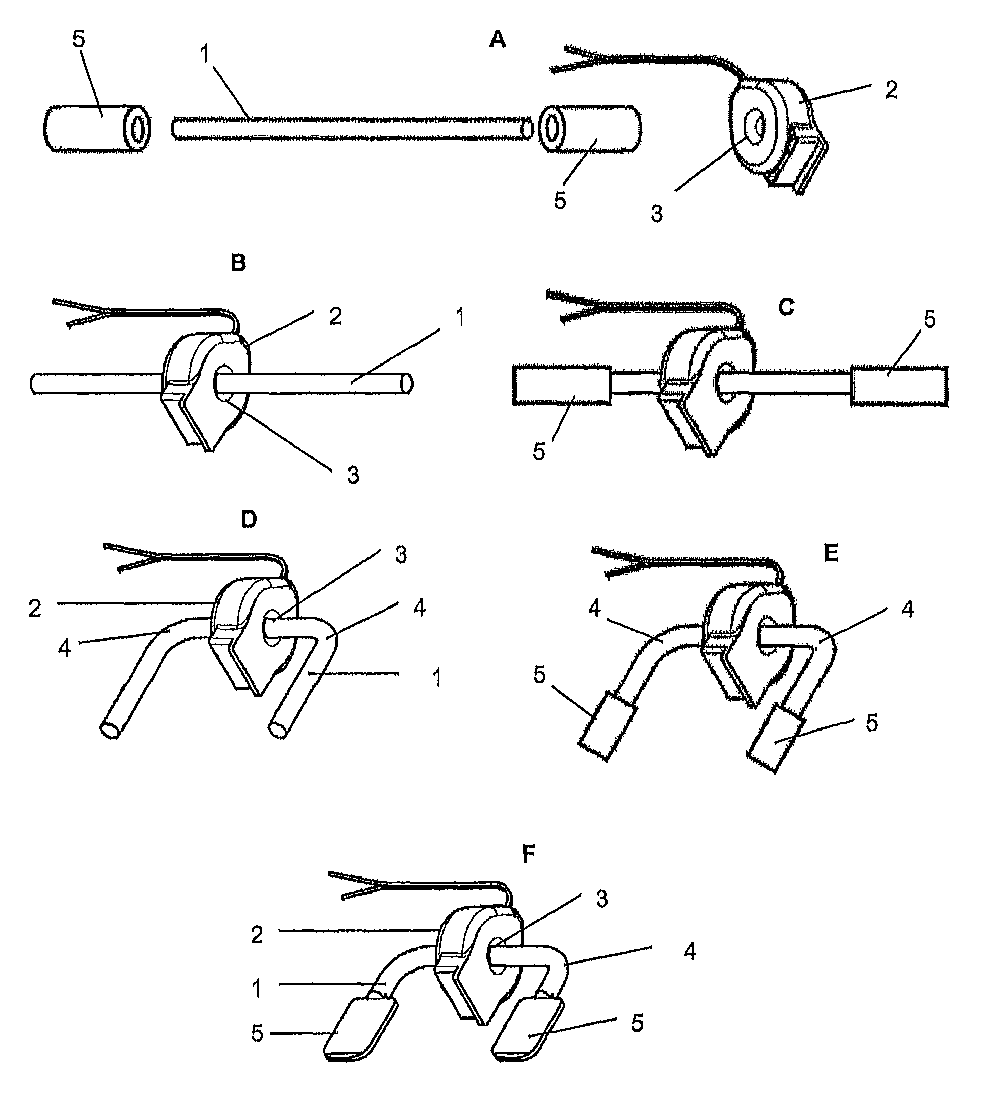
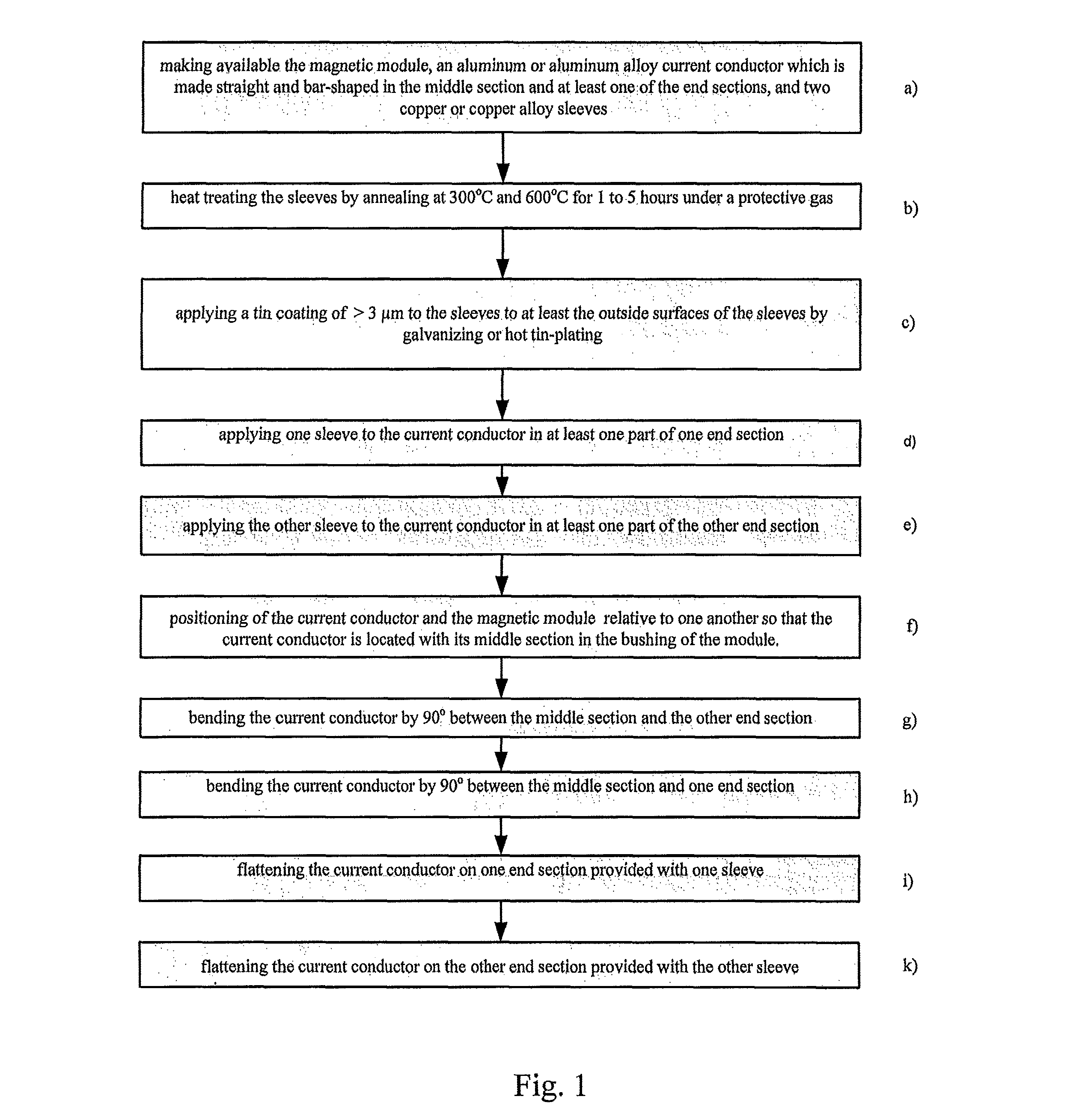
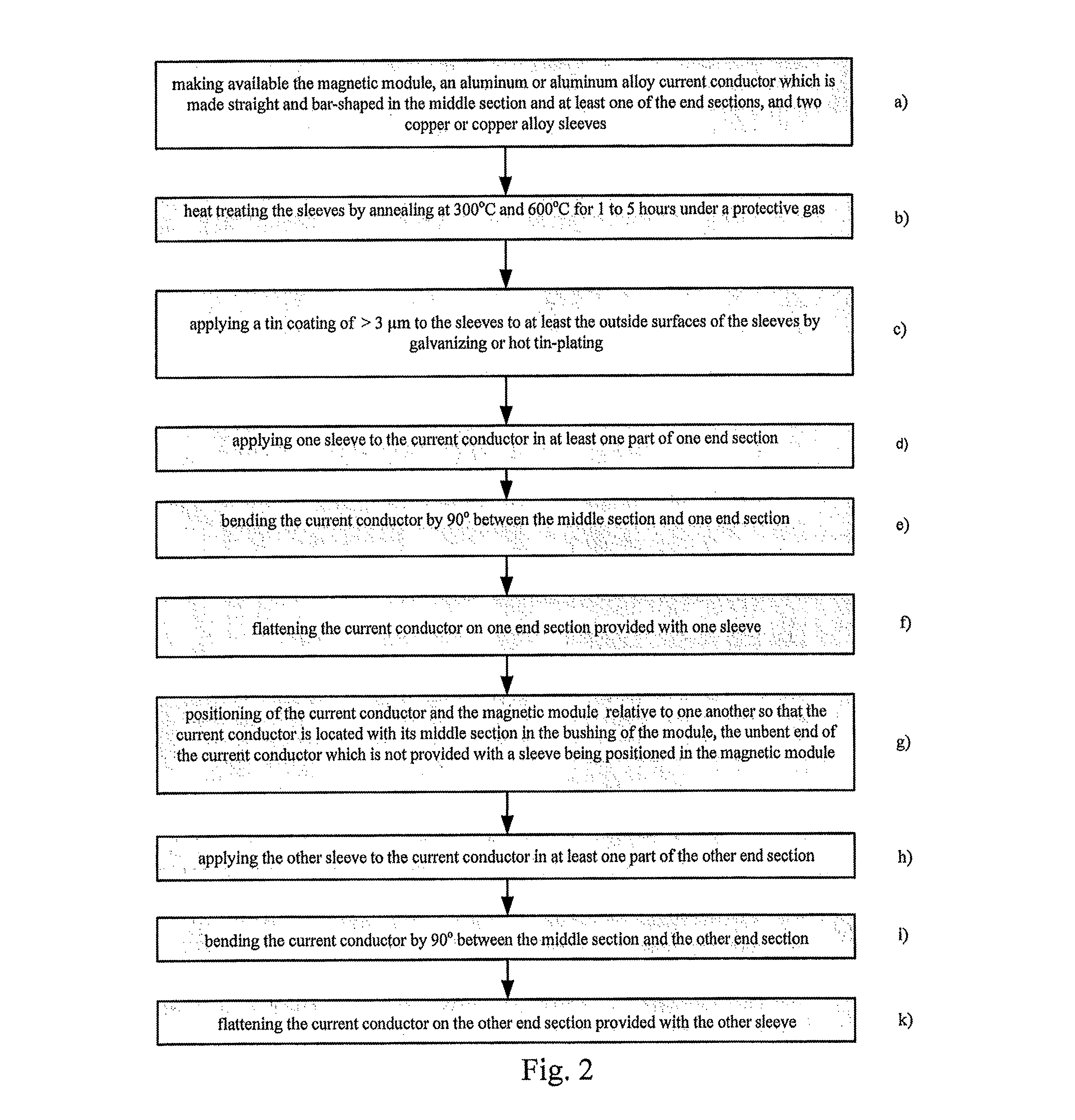
[0030]The method and the current metering device as described herein uses as the current conductor 1 a one-piece aluminum or aluminum alloy body which on its ends is provided with copper or copper alloy sleeves 5 which can optionally be coated at least on their outer surfaces with tin or a tin alloy layer. For final shaping of the resulting copper contact surfaces cold pressing can be used. Thus, expensive copper as the conductor material is quantitatively minimized, but the size of the current metering means is still kept as small as possible and no decrease in performance is found compared to an arrangement consisting of solid copper with respect to the reliability of the current conductor (e.g. primary conductor). This is achieved by limiting the use of copper to the regions of the primary current conductor where the properties which can be achieved with this material, such as for example very good contact resistance and minimum contact resistance as well as essentially negligibl...


PUM

PropertyMeasurementUnit
angleaaaaaaaaaa
temperatureaaaaaaaaaa
diameteraaaaaaaaaa

Abstract

A method for producing a current metering device with current conductor optionally made of aluminum or aluminum alloy, which has a middle section in the form of a bar and two end sections with flattened areas, and is bent between one end section at a time and the middle section, a magnetic module which has a bushing which holds the current conductor, and two copper or copper alloy sleeves which are applied at least to parts of the end sections of the current conductor.

Description

BACKGROUND[0001]1. Field[0002]Disclosed herein is a method for producing a current metering device which can be used for example in electricity meters or power meters.[0003]2. Description of Related Art[0004]For current metering or power metering, various electronic electricity meters are known which are increasingly replacing mechanical Ferraris meters in industry and the household and which meter current with arrangements of different mechanical and electrical structure. In addition to current metering with measurement shunts, Rogowski coils or Hall elements, current transformers based on soft magnetic annular cores, especially annular band cores, as magnetic modules, are common in electricity meters, A magnetic module (current transformer, transformer) causes electricity mains isolation and delivers a precise measurement quantity in the form of a signal voltage to a load resistor, The demands for amplitude accuracy, phase accuracy, and linearity are established by IEC 62053, −21,...

Claims


Application Information

Patent Timeline
Patent Type & Authority Patents(United States)
IPC IPC(8): G01R3/00
CPCH01F38/30H01F27/06H01F41/10Y10T29/49004Y10T29/49007Y10T29/49181
Inventor BRUNNER, MARKUS
Owner VACUUMSCHMELZE GMBH & CO KG
Why Eureka
Try Eureka