Diversity reception device and diversity reception method

a technology of diversity and reception device, applied in the field of diversity reception device and diversity reception method, can solve the problems of demodulated signal, expectation, poor maximal-ratio combining results, and inability to obtain excellent maximal-ratio combining results

Active Publication Date: 2014-08-26
LAPIS SEMICON CO LTD
View PDF6 Cites 0 Cited by
  • Summary
  • Abstract
  • Description
  • Claims
  • Application Information

AI Technical Summary

Benefits of technology

[0011]In consideration of the above, the present invention provides a diversity reception device and diversity reception method that may, in diversity reception with plural branches, combine demodulated signals of the branches with suitable weightings.
[0013]The correlation unit of the present aspect generates a correlation signal that is unrelated to the level of the received signal. Therefore, the receiving condition may be determined from the level of the correlation signal at a time position at which the correlation signal is at a peak (hereinafter referred to as the peak position), without being affected by the level of the received signal or the level of the demodulated signal. Accordingly, the present invention may suitably control weighting factors regardless of levels of received signals and levels of demodulated signals. That is, the resistance of detection to weakness of wanted waves and the like is relatively strong.
[0015]In the present aspect, because a weighting factor may be controlled by the period (time interval) of the time positions at which the correlation signal level is at peaks, the weighting factors may be suitably controlled regardless of the levels of the received signals and the levels of the demodulated signals. Therefore, the resistance of detection to weakness of wanted waves and the like is relatively strong.
[0017]In the present aspect, the weighting factor is controlled using the ratio between the level of the correlation signal at the time position at which the correlation signal level is at a peak and the integral of the level of the correlation signal from the peak position one cycle before that peak position to that peak position. Therefore, the weighting factors may be suitably controlled regardless of the levels of the received signals and the levels of the demodulated signals. Accordingly, the resistance of detection to weakness of wanted waves and the like is stronger. Here, the ratio between the peak level and the integral value is found regardless of whether or not the correlation section generates a correlation signal that is related to the level of the received signal. Therefore, the weighting factors may be controlled without being affected by levels of the received signals.

Problems solved by technology

However, when carriers are weighted and combined in accordance with reception levels, the modulation results of branches with reception levels at which reception is not possible, which are actually unwanted, may be combined at large weightings.
Thus, the demodulated signal may, contrary to expectation, be worsened and excellent maximal-ratio combining results may not be obtained.
However, the gain control value applied to an amplifier in a tuner, which is an analog circuit, and the actual gain (i.e., how large the gain is controlled to be in practice) have an error difference.
In a diversity receiver with plural branches, because there are differences in actual gains with respect to gain control of the tuners of the respective branches, it is difficult to implement excellent weighting by conversion from RSSI values, gain control values or the like.
Further, if unwanted broadcasts or unwanted waves are input to a particular branch, the power level is increased by these unwanted waves in an amount corresponding to the unwanted waves, this is reflected in the gain control, and the combining may be applied with an erroneous weighting.
However, in the diversity reception device recited in the above reference, because the reliability values (weightings) are found using pilot signals output from the equalization section, there is a problem with optimization of the weightings if there is a branch in a receiving condition in which the reception level of wanted waves that are required may not be guaranteed.
Therefore, the reliability value is affected by reception levels, and maximal-ratio combining with excellent weightings may not be possible.

Method used


Image

  • Diversity reception device and diversity reception method
  • Diversity reception device and diversity reception method
  • Diversity reception device and diversity reception method

Examples


first exemplary embodiment -

[0046]-First Exemplary Embodiment-

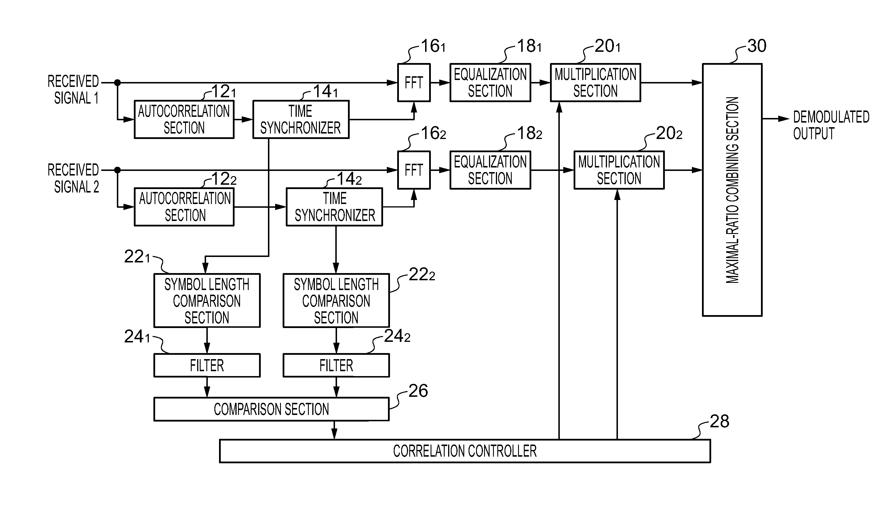
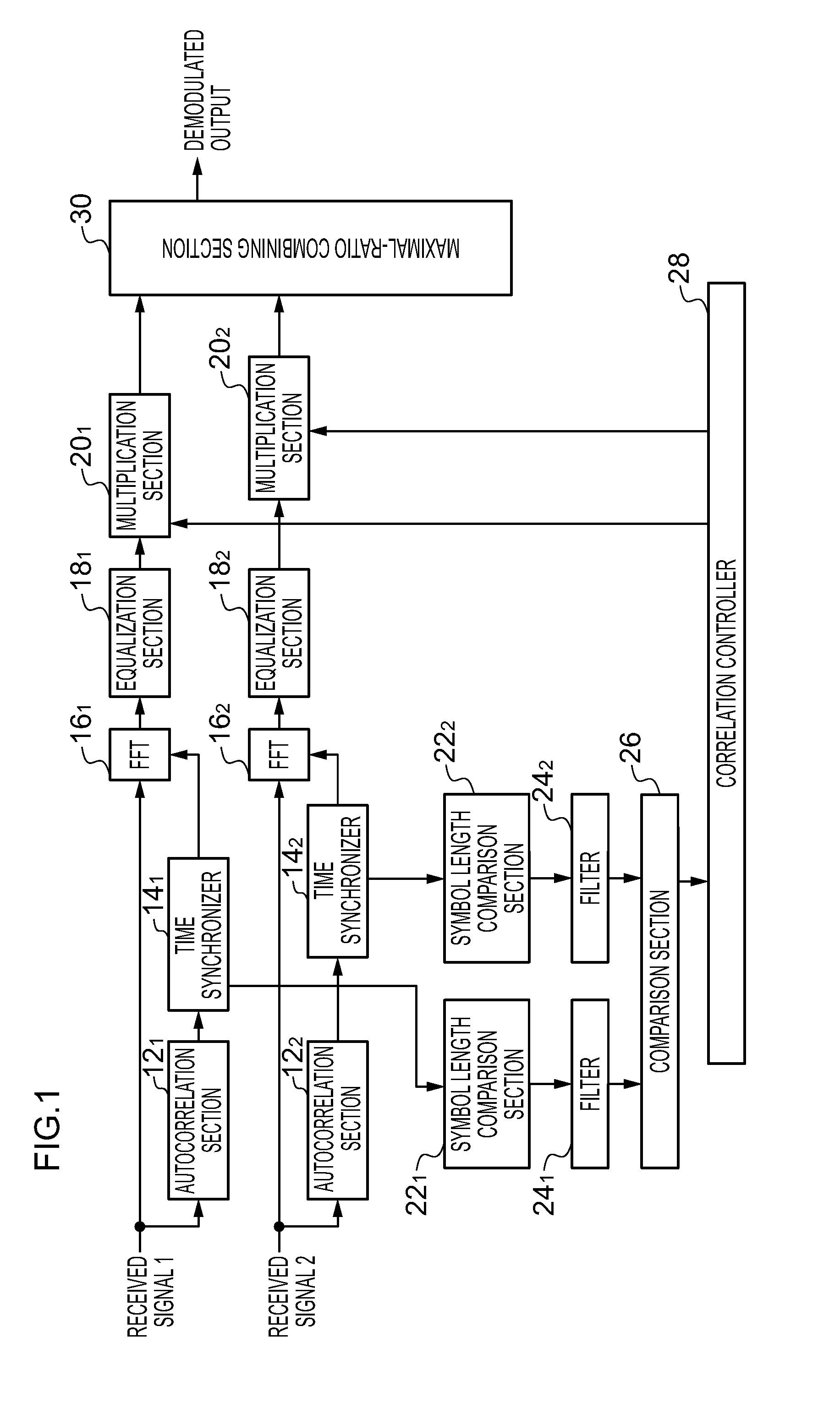
[0047]FIG. 1 is a diagram illustrating structure of a diversity reception device relating to a first exemplary embodiment, which diversity-receives orthogonal frequency division multiplexing (OFDM) signals. The diversity reception device of the present exemplary embodiment is described as being a device that includes two branches, a first branch and a second branch. Herein, processing sections (reception systems) for processing received signals that are provided in correspondence with respective antennas are referred to as branches.

[0048]The diversity reception device relating to the present exemplary embodiment is provided, at each branch, with an autocorrelation section 12, a time synchronizer 14, a fast Fourier transform section (FFT) 16, an equalization section 18, a multiplication section 20, a symbol length comparison section 22, and a filter 24. In FIG. 1, in order to distinguish between structural elements of the first branch and structural ...

second exemplary embodiment

[0088]-Second Exemplary Embodiment-

[0089]FIG. 6 illustrates structure of a diversity reception device of a second exemplary embodiment. In the diversity reception device of the present exemplary embodiment, the diversity reception device with two branches that is illustrated in the first exemplary embodiment is generalized to a diversity reception device with n branches (n being an integer that is at least two). The structures corresponding to each branch are the same as in the first exemplary embodiment. A concrete example of operation of the comparison section 26 and correlation controller 28 relating to the present exemplary embodiment is now described in detail.

[0090]The comparison section 26 relating to the present exemplary embodiment finds each of the following (A) to (D) from the filter outputs of the branches.

[0091](A) The smallest value of the filter outputs of all the branches (hereinafter referred to as the smallest filter output)

[0092](B) Respective differences between ...

third exemplary embodiment -

[0125]-Third Exemplary Embodiment-

[0126]FIG. 9 illustrates structure of a diversity reception device relating to a third exemplary embodiment. The diversity reception device of the present exemplary embodiment includes n branches (n being an integer that is at least two) and controls the gains of the branches using, instead of the peak time length, a ratio between a power level (peak level) at a peak position of the correlation signal and an integral of the level of the correlation signal in a time period from the preceding peak position (one cycle before) to the current peak position.

[0127]In FIG. 9, structural elements that are the same as in FIG. 6 are assigned the same reference numerals and descriptions thereof are omitted or simplified. Herebelow, structural elements that differ from FIG. 6 are described in detail.

[0128]The diversity reception device relating to the present exemplary embodiment is provided with, at each branch, the autocorrelation section 12, a time synchroniz...


PUM


Abstract

A diversity reception device includes branches, a controller and a combining section. Each branch includes a correlation section that generates a correlation signal that represents a correlation between a received signal and a delayed signal or between the received signal and a reference signal, where the correlation signal level disregarding the received signal level, a time position detector that detects time positions at which the level of the correlation signal is at a peak, a demodulation section that demodulates the received signal, and a multiplication section that multiplies the demodulated signal with a weighting factor. The controller controls the weighting factor on the basis of the respective levels of the correlation signals at the detected time positions. The combining section combines, by adding, the respective demodulated signals of the branches subsequent to the demodulated signal of each branch being multiplied with the weighting factor.

Description

CROSS-REFERENCE TO RELATED APPLICATION[0001]This application is based on and claims priority under 35 USC 119 from Japanese Patent Application No. 2010-183070 filed on Aug. 18, 2010, the disclosure of which is incorporated by reference herein.BACKGROUND[0002]1. Technical Field[0003]The present invention relates to a diversity reception device with a plural number of branches and a diversity reception method.[0004]2. Related Art[0005]In recent years, orthogonal frequency division multiplexing (OFDM) modulation systems and the like have been employed as modulation systems for terrestrial digital broadcasting. In an OFDM system, symbols are transmitted using plural sub carriers (carrier waves) with different center frequencies. The meaning of the term “symbol” herein is intended to include a single set of data transmitted in one cycle of modulation. A symbol period is constituted by appending a guard period to an effective symbol period. In an OFDM system, the effect of multipath inter...

Claims


Application Information

Patent Timeline
Patent Type & Authority Patents(United States)
IPC IPC(8): H04B1/00H04B7/08H04L25/02H04L25/03H04L27/26
CPCH04B7/0857H04L2025/03426H04L27/2647H04L25/03159H04L25/022
Inventor AKAHORI, HIROJI
Owner LAPIS SEMICON CO LTD
Why Eureka
Try Eureka