Sliding bearing and construction machine provided with same

a technology of sliding bearings and construction machines, applied in the direction of sliding contact bearings, soil shifting machines/dredgers, mechanical apparatus, etc., can solve the problems of uneven wear, seizure, scratching, etc., and achieve excellent lubrication performance, excellent strength, and small porosity of sintered metal for lubrication oil retention

Inactive Publication Date: 2014-09-02
NIHON KENKI CO LTD
View PDF32 Cites 7 Cited by
  • Summary
  • Abstract
  • Description
  • Claims
  • Application Information

AI Technical Summary

Benefits of technology

[0026]According to the present invention, the shaft part that is in sliding contact with the bush has the grease feeding pathway in communication with the sliding surface of the bush so that it is possible to feed the grease to the sliding surface of the bush from the outside in a desired manner. Also, because the bush is formed from the porous sintered metal and the decomposition catalyst is provided at the sliding surface of the bush, the grease supplied to the sliding surface of the bush is decomposed by the decomposition catalyst and the base oil is separated. Then the base oil can easily penetrate the bush from the sliding surface of the bush and is retained in the pores of the bush. Consequently, it is possible to maintain excellent lubrication performance for a long period of time without bush replacing work and lubrication oil impregnating work. Further, because the porosity of the sintered metal for retention of the lubrication oil can be small, the bush has excellent strength.

Problems solved by technology

Thus, the contact surfaces (sliding surfaces) between the bushes and shaft parts encounter severe lubrication conditions, and therefore seizure, scratching, uneven wear and other problems are likely to occur due to shortage of lubrication.

Method used


Image

  • Sliding bearing and construction machine provided with same
  • Sliding bearing and construction machine provided with same
  • Sliding bearing and construction machine provided with same

Examples


Embodiment Construction

[0032]Embodiments according to the present invention are now described with reference to the accompanying drawings.

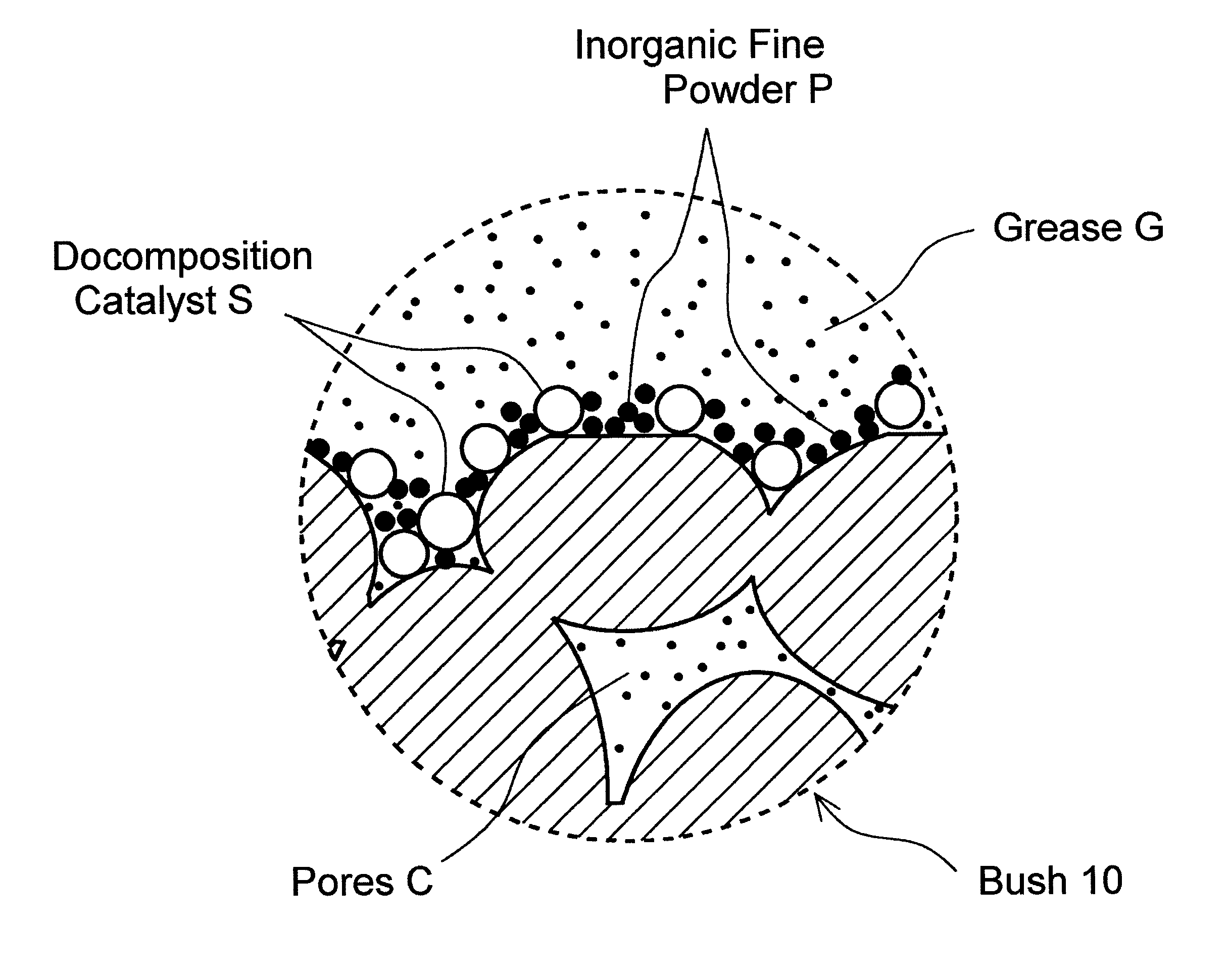
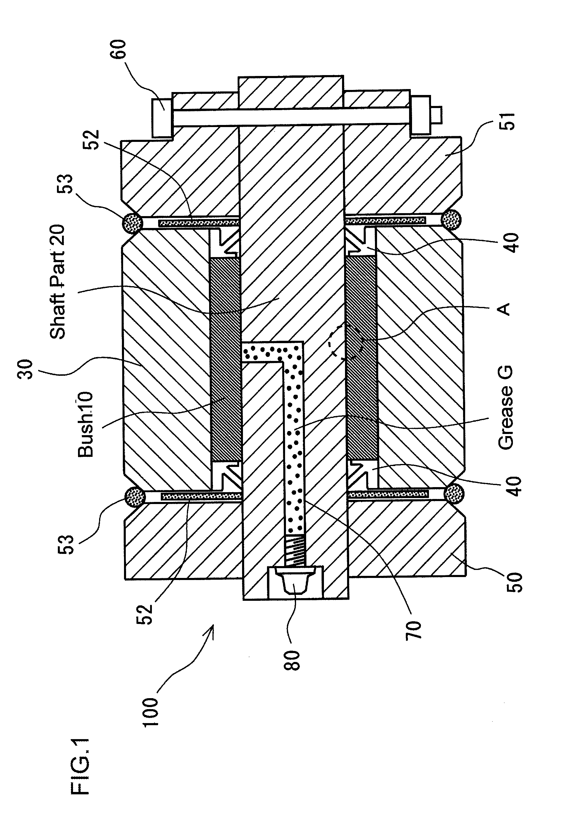
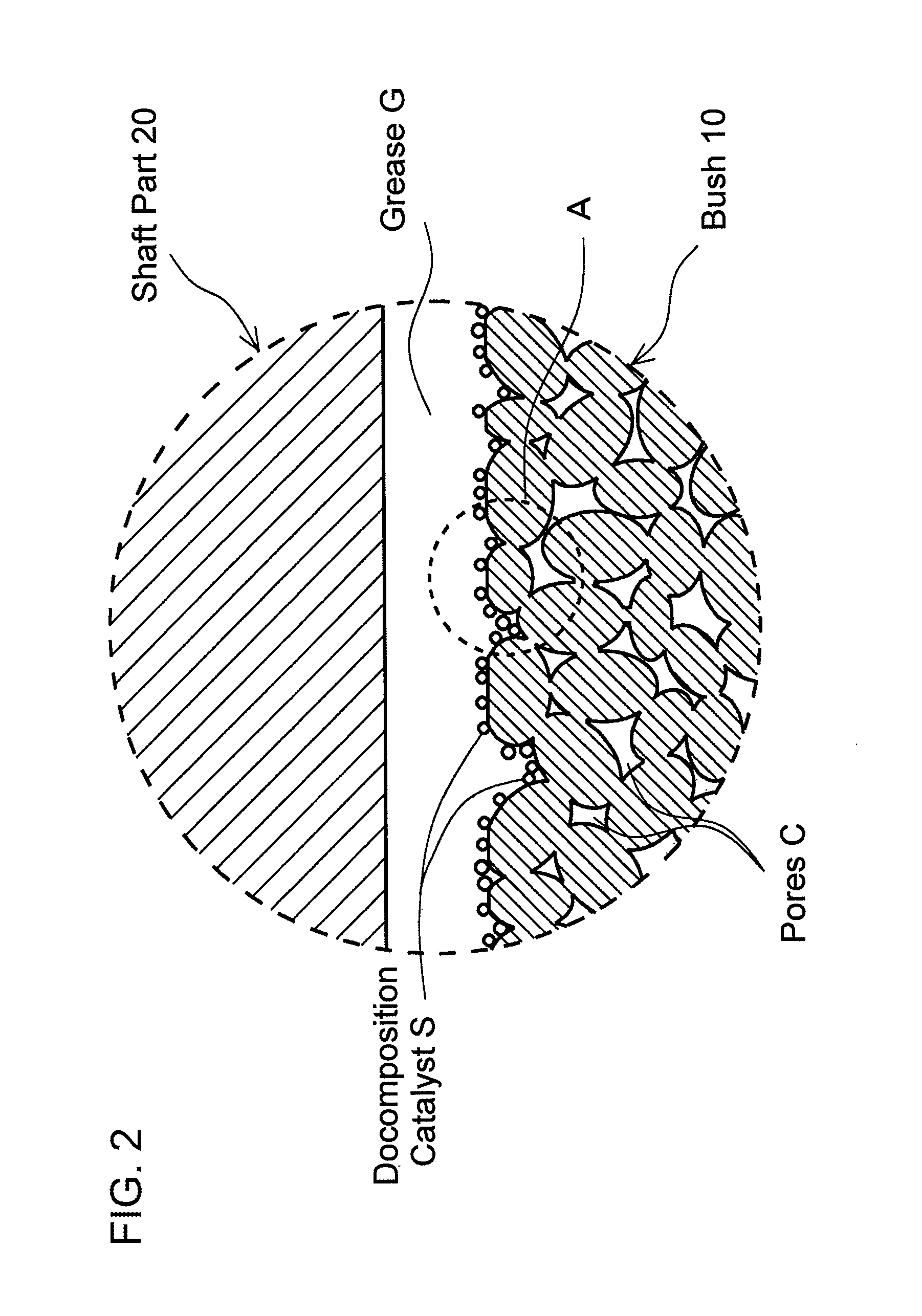
[0033]FIG. 1 shows a vertical cross-sectional view of one embodiment of a sliding bearing 100 according to the present invention. In the drawings, reference numeral 10 designates a cylindrical bush with both ends open. A circular-rod-shaped shaft part 20 rotatably extends through an axial hole of the bush 10. The inner surface of the bush 10 is in sliding contact with the outer surface of the shaft part 20 under a high contact pressure (for example, several MPa to several tens of MPa) at a slow speed (for example, 3.0 m / min or less), and these surface define the sliding surfaces.

[0034]The bush 10 is received in a boss 30. Inside the boss 30, dust seals 40 and 40 are press-fitted at both ends of the bush 10 respectively to prevent invasion of foreign matters. Brackets 50 and 51 are provided at both end faces of the boss 30 respectively, and shims 52 and 52 are interposed...


PUM

PropertyMeasurementUnit
speedaaaaaaaaaa
contact pressureaaaaaaaaaa
sliding speedaaaaaaaaaa

Abstract

Provided are a novel sliding bearing and a construction machine provided with same, the sliding bearing being capable of maintaining an excellent sliding performance over a long period of time and exhibiting an excellent strength. A sliding bearing includes at least a brush and a shaft part, the shaft part being provided with a grease feeding pathway for feeding grease from the exterior to the sliding surfaces of the shaft part and the bush, the bush being formed from a porous sintered metal, and a decomposition catalyst being adhered to the sliding surface of the bush.

Description

TECHNICAL FIELD[0001]The present invention relates to a sliding bearing that is used for a wide variety of general machines, and particularly to a sliding bearing that can be used under severe lubrication conditions including high contact pressure and a slow speed sliding (e.g., a sliding bearing that is used in a construction machine such as hydraulic excavator or power shovel), and also relates to a construction machine equipped with such sliding bearings.BACKGROUND ART[0002]In general, a construction machine such as a hydraulic excavator has a number of sliding bearings that are used under conditions including high contact pressure and slow speed sliding. For example, as shown in FIG. 5, a conventional hydraulic excavator 200 is configured to have an arm 210, with a bucket 220 being rotatably connected to a distal end of the arm 210. The arm and bucket are driven by a plurality of hydraulic cylinders 230 respectively. Coupling portions between the arm 210 and bucket 220 as well a...

Claims


Application Information

Patent Timeline
Patent Type & Authority Patents(United States)
IPC IPC(8): F16C33/02B22F3/11B22F5/10C22C1/08C22C38/00E02F9/00F16C11/04F16C17/02F16C33/10F16C33/12
CPCE02F9/006F16C11/045F16C33/128C22C1/08B22F3/1146F16C33/102C22C38/00B22F5/10F16C17/02F16C2350/26Y10S384/902
Inventor AKITA, HIDEKIGOKITA, OSAMUSAKURAI, SHIGEYUKINAGAI, YASUCHIKA
Owner NIHON KENKI CO LTD
Why Eureka
Try Eureka