Apparatus and method for determining eye gaze from stereo-optic views

a stereo-optic view and eye gaze technology, applied in the field of optical instrument design, can solve the problems of inability to easily place objects that users may need to work with between the face and the optics, the limited light level of the panel mounted system, and the potential limitations or drawbacks of single light sensor us

Inactive Publication Date: 2014-09-02
CORTICAL DIMENSIONS LLC
View PDF3 Cites 443 Cited by
  • Summary
  • Abstract
  • Description
  • Claims
  • Application Information

AI Technical Summary

Benefits of technology

[0015]In another embodiment, the invention incorporates a novel single lens stereo design with stepped mirrors for tracking the eye during which stereo images of the eye are acquired. The mirror system may be a planar parallel plate that is switched between positions about the optical axis of the device. In a further embodiment, the mirror is a segmented mirror with segment elements stepped between positions by micromechanical actuators that are synchronized with the camera action. In some embodiments the microelectro-mechanical mechanisms may be bimorph piezoelectric or piezoelastric devices. In other embodiments, the actuators may be electroactive polymer, in particular dielectric electromer. In a still further embodiment, the mirror segments may be incremented (i.e., stepped) between multiple positions about the optical axis providing multiple stereo views about a baseline, resulting in depth maps of higher accuracy with the large number of extra images captured at multiple plate poses. These depth maps may be used with motion stereo-optics for improved stereo image processing.
[0028]The invention is easily extended to the simultaneous tracking of both eyes allowing the measurement of the optical convergence point in the three dimensional workspace either real or virtual. For this reason, the invention has applications in the field of medicine diagnostics of neurological disorders by ocular functions such as the evaluation by eye movements of the severity of head trauma, and for this purpose may be part of desk mounted fixture or an addition to a computer screen used in diagnostics. The invention has applications to gaze-contingency displays operated by ocular gaze point of regard and fixation duration, such as used for control of computerized machinery from video displays. Here, the invention determines the ocular fixation dwell time; this parameter may be used to pre-select a display icon element. These advantages make the invention particularly attractive for measuring ocular functions with virtual image display overlays such as on helmet mounted displays or night vision goggles. Further, the invention may be incorporated into panel mounted displays and head-free sensor arrays for similar purposes. Continuing, the invention may be incorporated into hand-held electronic devices such as cellular phones and data pads among others to track the user's interest in device video display icons; a device mounted accelerometer may be used to locate the face and consequently the eye orbit in the camera view during hand movements. Scene processing software may be used to determine the user's interest in the tracked icons from facial expressions deduced from automated analysis of isolated facial features.

Problems solved by technology

Although such oculometers provide an indication of eye position and, therefore, gaze direction, the use of a single light sensor presents various potential limitations or drawbacks.
The panel mounted system is limited to low ambient light levels and objects that the user may need to work with cannot be readily placed between the face and the optics.
Excessive head movements and interference of the optical path by facial features (such as the user's nose) are not tolerated.
The accuracy of the technology is roughly about + / − one degree in practice and is limited by the processing of the pupil image from which the image centroid and orientation are determined; these parameters are used to estimate the angular location of the eye relative to the camera.
However, a problem is the image distortion caused by corneal surface refraction.
The accuracy decreases with side-view because of the non-uniform distortions in the pupil image caused by the corneal surface refraction with pupil offset.
This non-linearity in distortion causes the centroid computed for the image ellipsoid to be displaced from the centroid for the true image resulting in computational error, a problem the present technology does not correct.
Furthermore, the technology estimates only the principal axis of sight and does not account for the effect on sight direction of the torsional roll of the eye with accompanying vertical vergence eye movement that is induced during the tilting of the head a common occurrence during target tracking and user motion.
However, failing modeling of the user, the design may use a standard corneal model to correct for refraction.

Method used


Image

  • Apparatus and method for determining eye gaze from stereo-optic views
  • Apparatus and method for determining eye gaze from stereo-optic views
  • Apparatus and method for determining eye gaze from stereo-optic views

Examples


Embodiment Construction

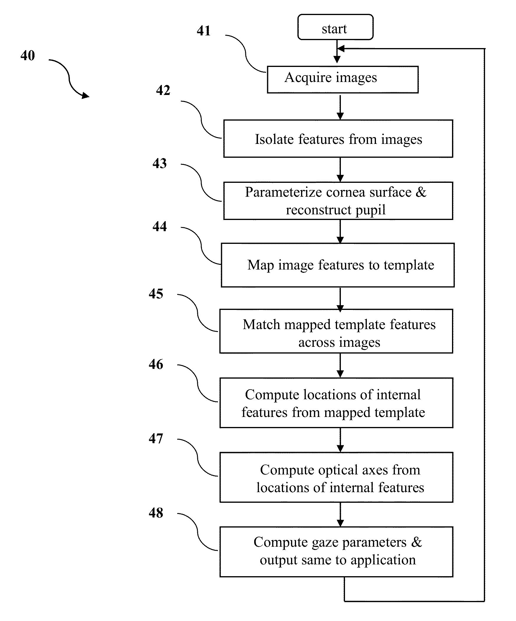
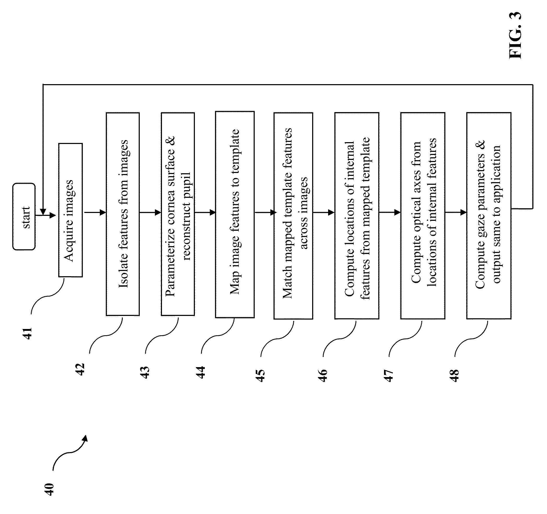
[0084]Disclosed herein are systems and methods for tracking an eye. More particularly, disclosed are an eye-tracking system and method that employ multiple views of the eye that provide image data that is processed to determine at least a gaze direction of an eye.

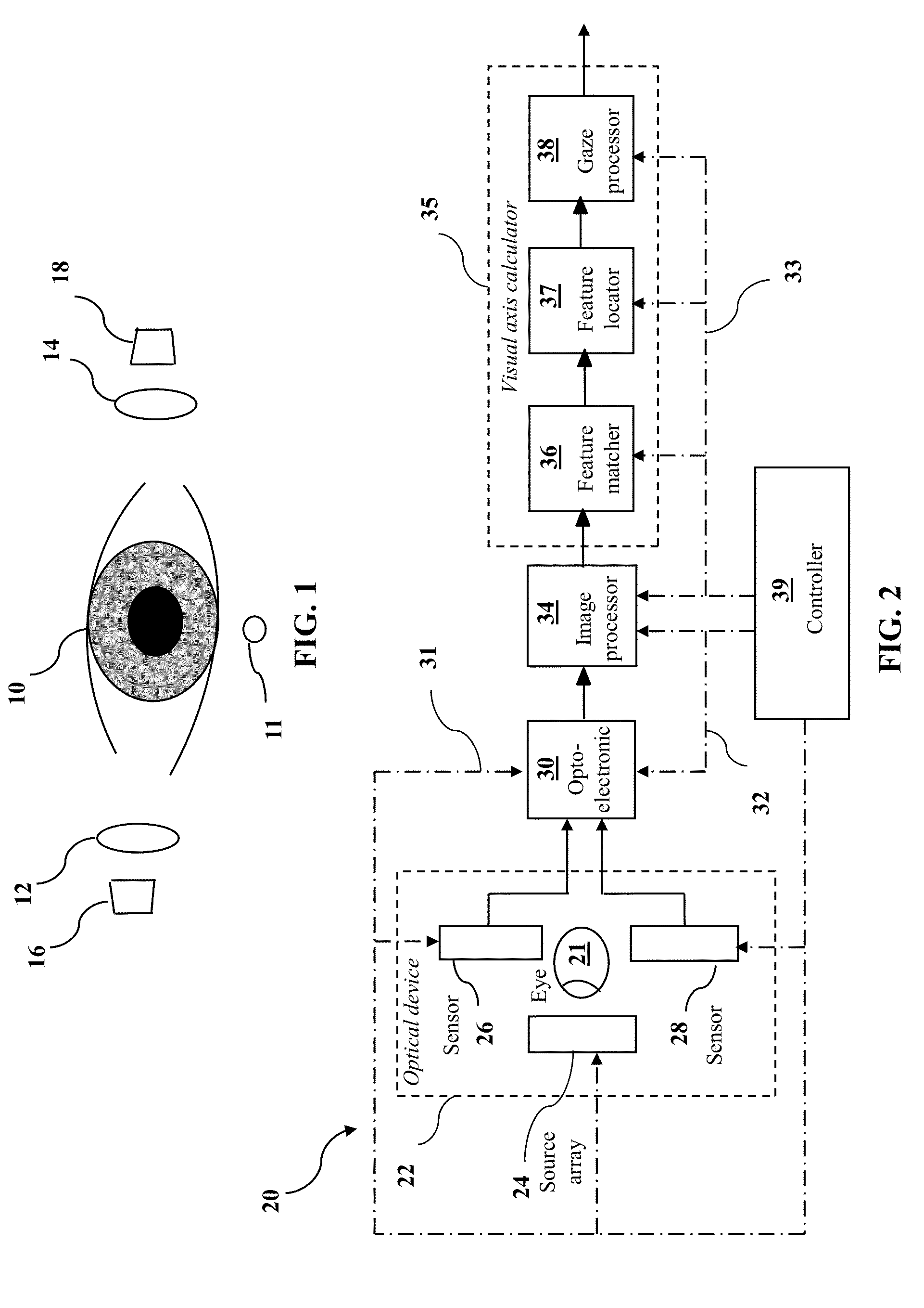
[0085]Referring now to the drawings, in which like numerals indicate corresponding parts throughout the several views, FIG. 1 illustrates an eye 10 of a user (e.g., a wearer of an eye-tracking mechanism) illuminated by a light source 11. Positioned on opposite sides (e.g., opposed lateral sides) of the eye 10 are optical systems 12, 14 and light sensors 16, 18. The optical systems 12, 14 each comprise one or more lenses and / or mirrors that are used to direct and focus light that reflects off of the eye 10 on their associated light sensors 16, 18. The light sensors 16, 18 receive the reflected light (i.e., light rays), which is used to determine the gaze direction of the eye. More particularly, the light sensors 16, 18 gener...


PUM


Abstract

The invention, exemplified as a single lens stereo optics design with a stepped mirror system for tracking the eye, isolates landmark features in the separate images, locates the pupil in the eye, matches landmarks to a template centered on the pupil, mathematically traces refracted rays back from the matched image points through the cornea to the inner structure, and locates these structures from the intersection of the rays for the separate stereo views. Having located in this way structures of the eye in the coordinate system of the optical unit, the invention computes the optical axes and from that the line of sight and the torsion roll in vision. Along with providing a wider field of view, this invention has an additional advantage since the stereo images tend to be offset from each other and for this reason the reconstructed pupil is more accurately aligned and centered.

Description

CROSS-REFERENCED TO RELATED APPLICATION[0001]This application claims priority under 35 U.S.C. 120 from U.S. patent application Ser. No. 13 / 374,286, filed 20 Dec. 2011, naming Christopher C. Smyth as inventor, and entitled: “Apparatus and Method for Determining Eye Gaze from Stereo-Optic Views”; this patent application is incorporated herein for all purposes.BACKGROUND[0002]1. Technical Field[0003]The invention has application in the field of oculometer design. Oculometers may be used to measure the eye gaze direction, as well as the fixation duration and dual eye binocular convergence point. Such oculometers have many potential applications in the medical, scientific, engineering, manufacturing, military, and entertainment domains. Example applications include use of an oculometer as a tool for the medical diagnosis of ocular functions, as an aid to the paraplegic handicapped, for the measurement of ocular functions and workload in human factors studies, as a measure of subject trai...

Claims


Application Information

Patent Timeline
Patent Type & Authority Patents(United States)
IPC IPC(8): G06K9/00
CPCG06K9/00G06T7/0075G06K9/0061G06T7/0042G06T2207/10152G06T2207/30041G06T2207/10021G06T7/73G06T7/593G06V40/193
Inventor SMYTH, CHRISTOPHER, CHARLES
Owner CORTICAL DIMENSIONS LLC
Why Eureka
Try Eureka