Cell front panel system

a technology of front panel system and cell, which is applied in the field of design, construction and installation of cell front panel system, can solve the problems of failure to provide, health and safety, detention and correctional facilities, etc., and achieve the effect of saving time in the overall construction process and simplifying the design, construction and installation process

Inactive Publication Date: 2014-09-16
LACK JR WILLIAM VOLLIS
View PDF7 Cites 1 Cited by
  • Summary
  • Abstract
  • Description
  • Claims
  • Application Information

AI Technical Summary

Benefits of technology

[0006]I disclose a design and method for constructing and installing a cell front panel system that simplifies the design, construction and installation of secure jail, prison, containment or detainment cell fronts. The construction design and method utilizes a steel cell front that is built of wall panels. The panels are manufactured and can be delivered to the site at a late date in the construction time frame, which allows for the building envelope to be closed in early on during the construction process. This invention allows for the panels to be pre-finished, further saving time in the overall construction process. The design of the panels is such that they can be brought into a building through standard door openings and erected with small hand tools requiring no on-site welding or the use of large cranes. All cell front connections are concealed from the cell interior making a secure facility.

Problems solved by technology

Currently, by and large, detainment and correctional facilities of all genres suffer overcrowded inmate populations residing under conditions that often compromise health and safety and fail to provide even a scintilla of dignity to the incarcerated no matter how egregious the event was that placed the inmate there.
Traditional methods of design, construction and installation of modern correctional facility cells resulted in scheduling challenges and delays.
These methods required one of two slow and cumbersome processes: either on-site welding for construction and installation; or off-site construction, then installation using large cranes to lower the cells through an open roof.
The traditional methods for building cell fronts were also slow due to on demand manufacturing with long delivery time frames.
All of these flaws resulted in an overall lengthy, uncertain and costly facility construction process.
Traditional cell fronts that were constructed off-site also had further flaws, including they did not allow for tolerances that vary in leveling, plumbness and dimensions.
This could result is the need for significant on-site modifications.
The size of the cell front would prohibit its use in restoration projects unless those projects where specifically designed to accommodate the cell front.
Furthermore, the design of these cells would make installation virtually impossible unless the second floor was installed after lower level cell fronts were installed.
Installation of a cell front on the first floor after installation of the second floor would be extremely cumbersome if not completely impractical.

Method used


Image

  • Cell front panel system
  • Cell front panel system
  • Cell front panel system

Examples


Embodiment Construction

[0026]The following detailed description is presented to enable any person skilled in the art to make and use the invention. For purposes of explanation, specific details are set forth to provide a thorough understanding of the present invention. However, it will be apparent to one skilled in the art that these specific details are not required to practice the invention. Descriptions of specific applications are provided only as representative examples. Various modifications to the preferred embodiments will be readily apparent to one skilled in the art, and the general principles defined herein may be applied to other embodiments and applications without departing from the scope of the invention. The present invention is not intended to be limited to the embodiments shown, but is to be accorded the widest possible scope consistent with the principles and features disclosed herein.

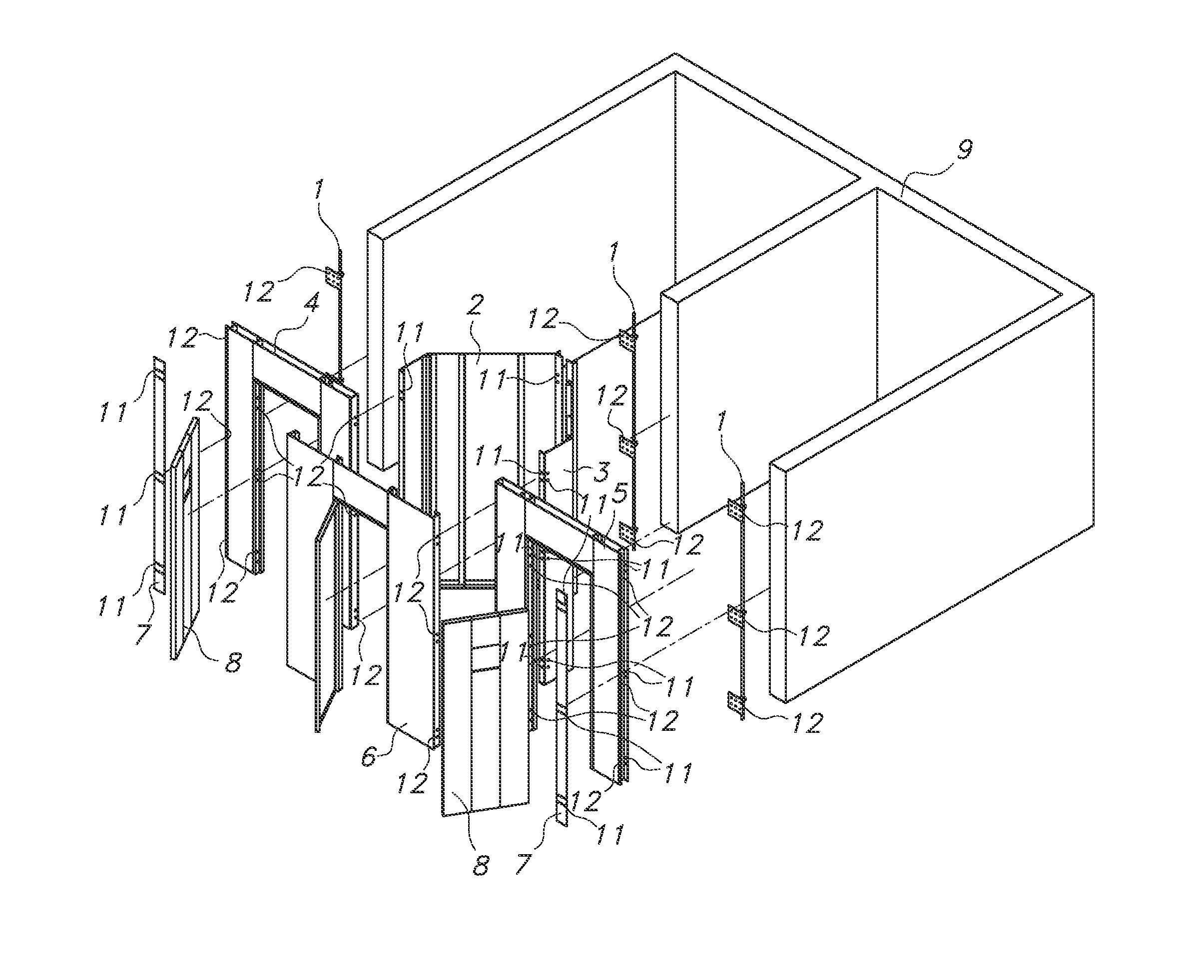
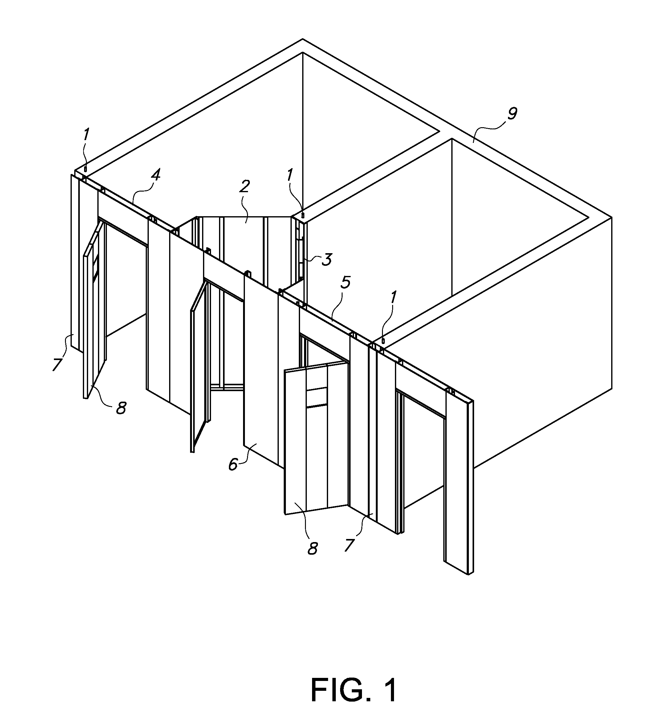
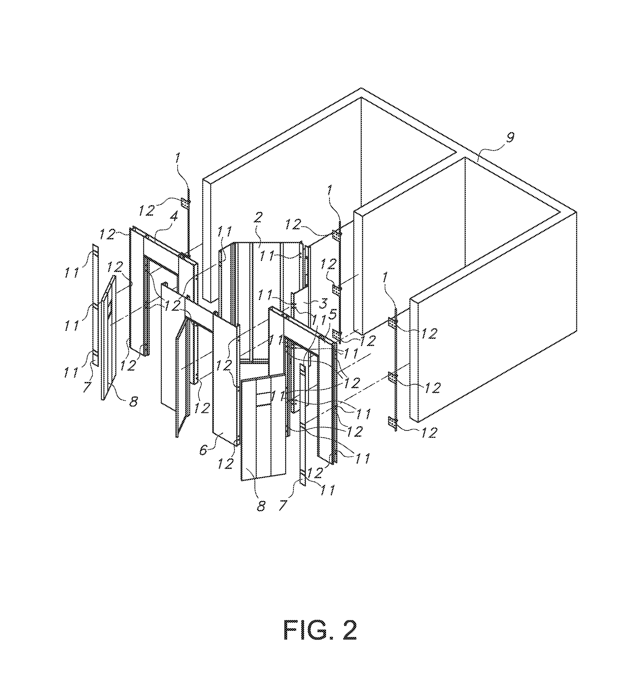
[0027]Referring to the drawings, FIG. 1 illustrates an exemplary embodiment of the cell front panel sys...


PUM


Abstract

I disclose a design and method for constructing and installing a cell front panel system that simplifies the design, construction and installation of secure jail, prison, containment or detainment cell fronts. This design and method allows for construction and installation of cell fronts to occur at any time during a facility construction, using only small hand tools and non-specialized workers.

Description

CROSS-REFERENCES TO RELATED APPLICATIONS[0001]This application claims the benefit of U.S. Provisional Application No. 61 / 629,214 filed Nov. 15, 2011 and is herein incorporated by reference in its entirety.FIELD OF THE INVENTION[0002]The present invention is generally directed toward the design, construction and installation of a cell front panel system.BACKGROUND OF THE INVENTION[0003]This invention arises as a result of the ubiquitous societal need to increase the size and number of available cells for short term and long term detainment and correctional facilities in order to accommodate the ever growing population of people behind bars. Currently, by and large, detainment and correctional facilities of all genres suffer overcrowded inmate populations residing under conditions that often compromise health and safety and fail to provide even a scintilla of dignity to the incarcerated no matter how egregious the event was that placed the inmate there. Many facilities, and the indivi...

Claims


Application Information

Patent Timeline
Patent Type & Authority Patents(United States)
IPC IPC(8): E04H3/06E04B1/38E04B2/74E04B2/82E04H3/08
CPCE04H3/08E04B1/38E04B2/7448E04B2/828
Inventor LACK, JR., WILLIAM, VOLLIS
Owner LACK JR WILLIAM VOLLIS
Why Eureka
Try Eureka