Heat exchanger apparatus for converting a shell-side liquid into a vapor

a technology of heat exchanger and liquid, which is applied in the direction of steam generation using hot heat carriers, steam generation using solar heat, etc., can solve the problems of hot spots, liquid water not being able to make surface contact with the outer surface, and lack of vapor blanketing, etc., to reduce the occurrence of vapor blanketing and increase the heat transfer rate.

Active Publication Date: 2014-09-16
HOLTEC INT
View PDF20 Cites 16 Cited by
  • Summary
  • Abstract
  • Description
  • Claims
  • Application Information

AI Technical Summary

Benefits of technology

[0008]The present invention eliminates or minimizes the occurrence of vapor blanketing while permitting the use of a dense tube bundle that does not require a larger pitch-to-diameter ratio. The present invention increases the heat transfer rate, and hence, the vaporization rate compared to the currently available designs.

Problems solved by technology

In existing steam generators, a deficiency known as vapor blanketing is prevalent.
Vapor blanketing occurs due to the high surface tension of steam, which causes the liquid water to be unable to make surface contact with the outer surface of the tubes of the tube bundle.
Since the shell-side liquid water is unable to make contact with the tubes at areas having vapor blanketing, the temperature of the tubes exceeds the thermal capacity of the shell-side liquid water, thereby creating a hot spot.
Vapor blanketing inhibits heat transfer and results in a reduced heat exchanger performance.
Previous attempts to address the vapor blanketing problem have been ineffective and inefficient.
This remedy requires the use of a much larger shell and therefore results in a much higher equipment cost.

Method used


Image

  • Heat exchanger apparatus for converting a shell-side liquid into a vapor
  • Heat exchanger apparatus for converting a shell-side liquid into a vapor
  • Heat exchanger apparatus for converting a shell-side liquid into a vapor

Examples


Embodiment Construction

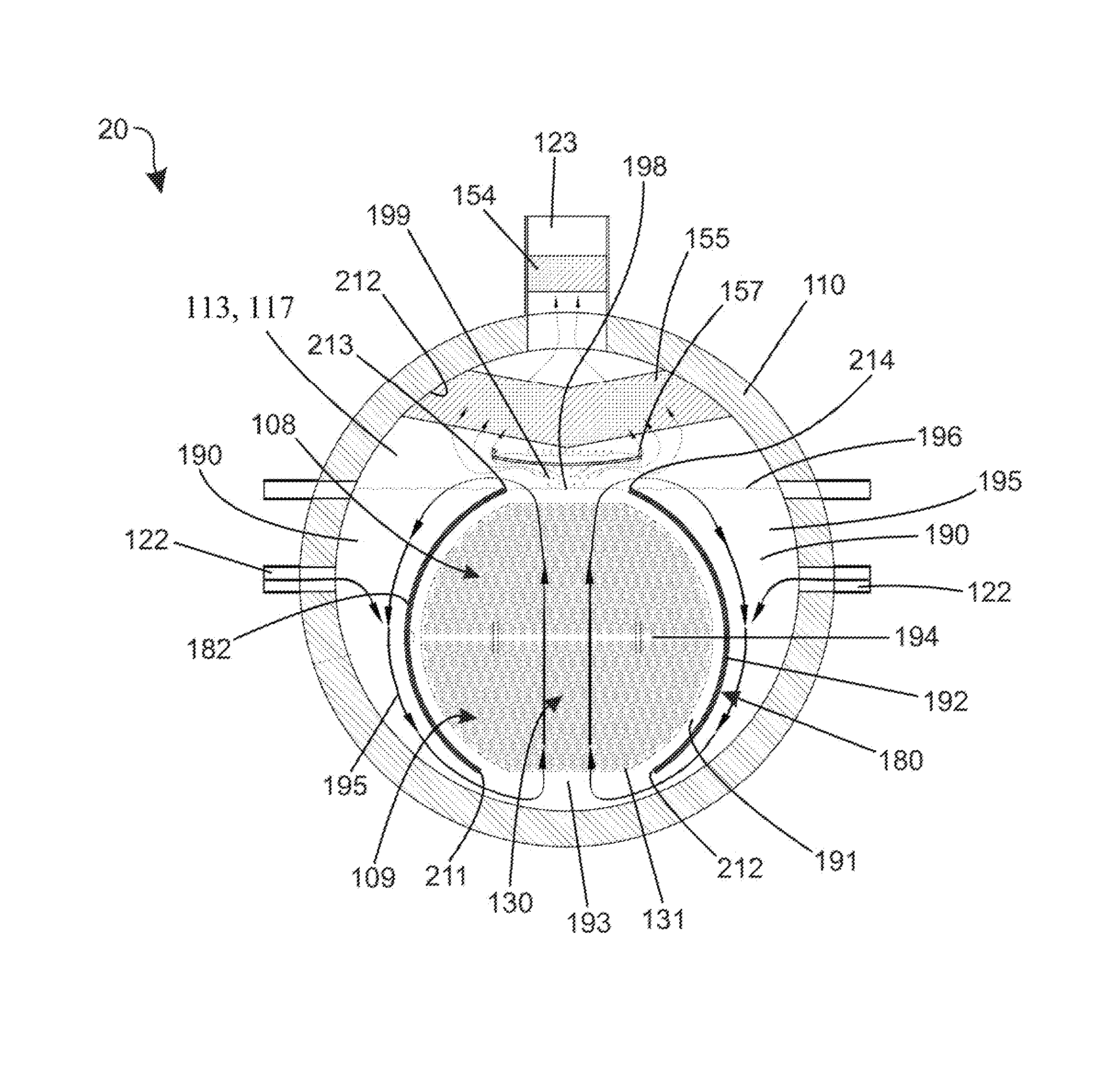
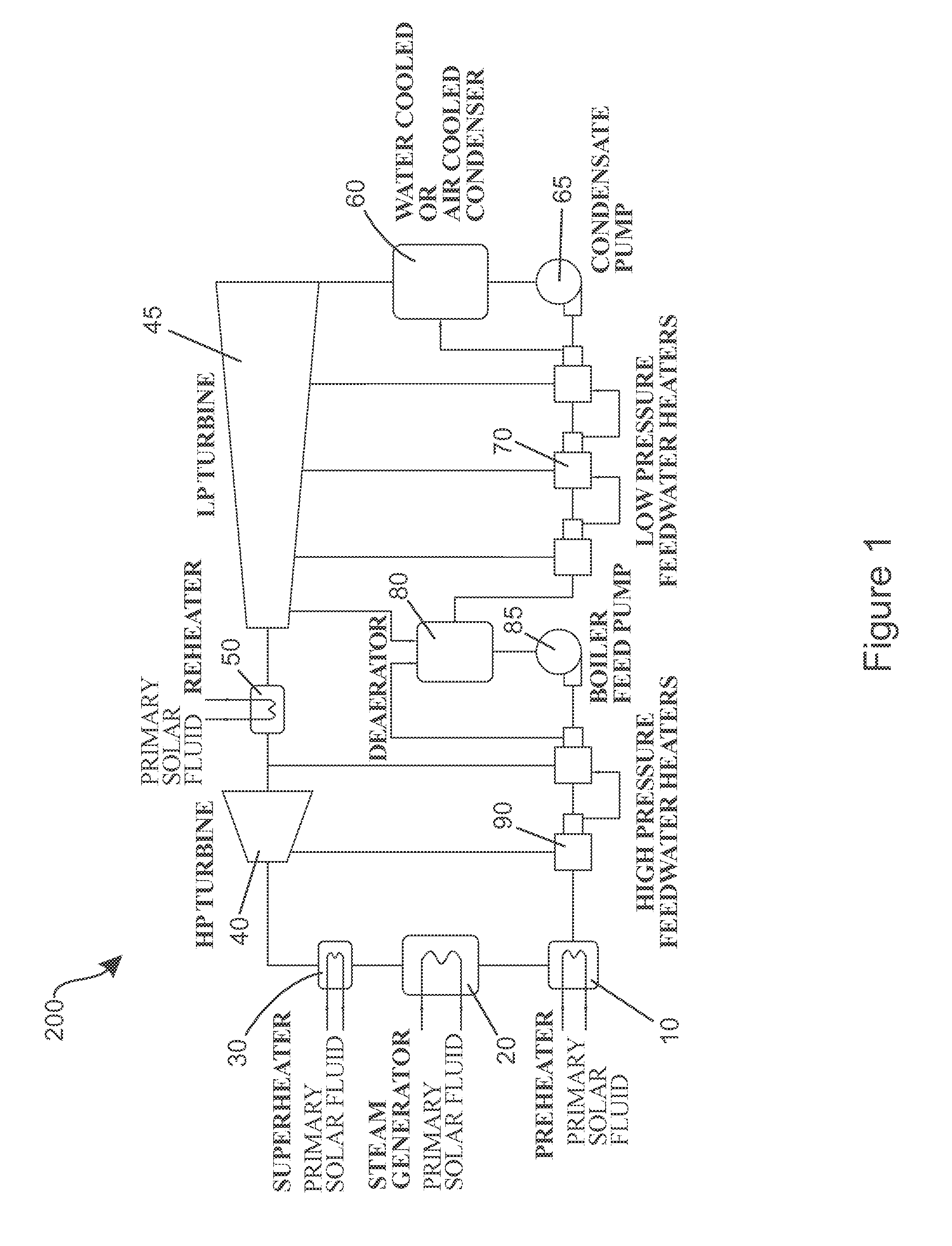
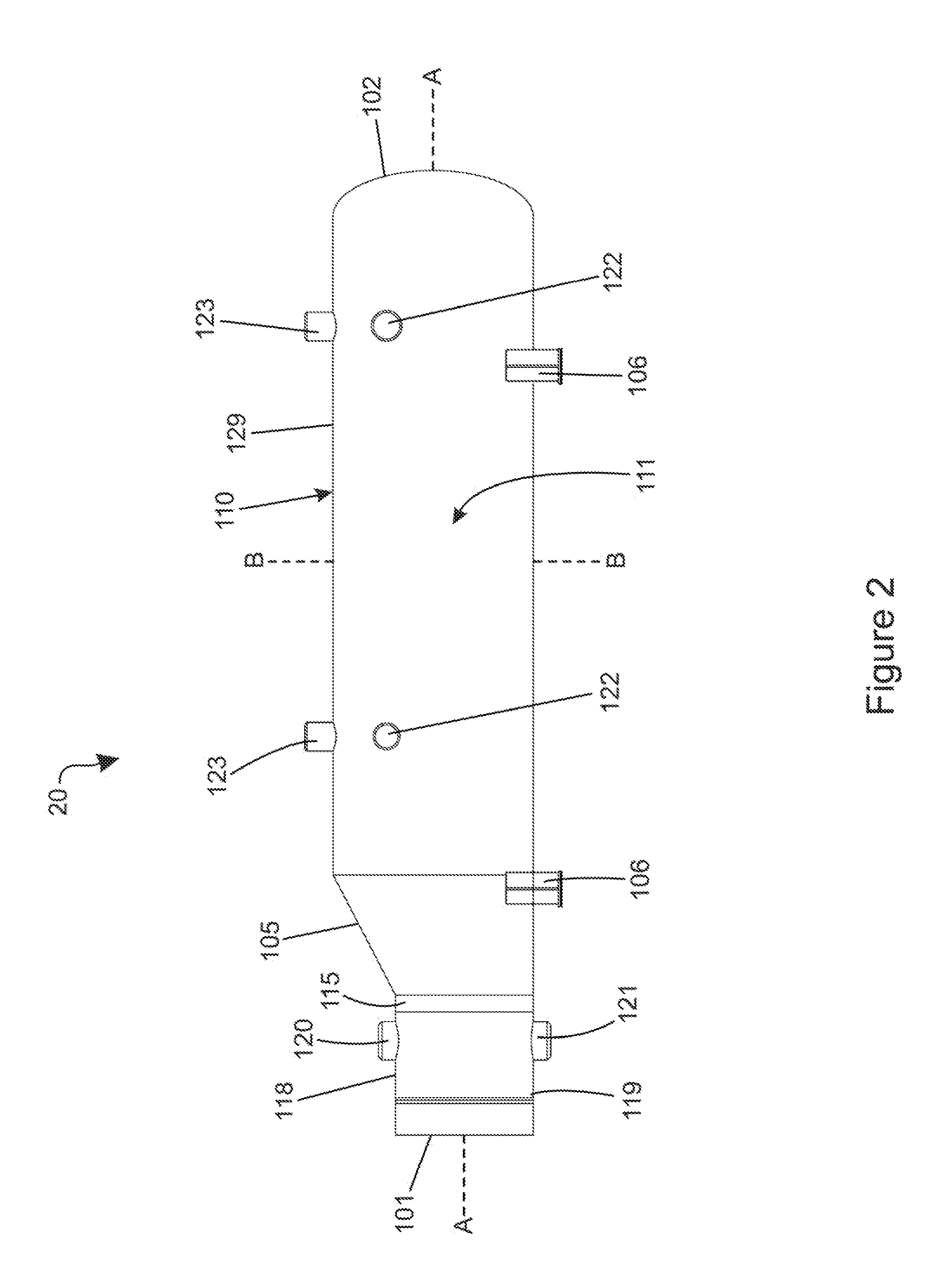
[0023]Referring to FIG. 1, a schematic of a solar power plant 200 is illustrated according to an embodiment of the present invention. While the invention is discussed in terms of (or incorporated into) a solar power plant 200, the invention is not so limited and can be used in any environment in which a heat exchanger is desired to convert liquid into a vapor.

[0024]The solar power plant 200 generally comprises a preheater 10, a steam generator 20, a superheater 30, a high pressure (HP) turbine 40, a reheater 50, a low pressure (LP) turbine 45, an air cooled condenser 60, a condensate pump 65, a low pressure feedwater heater 70, a deaerator 80, a boiler feed pump 85 and a high pressure feedwater heater 90. All of the aforementioned components of the solar power plant 200 are arranged and operably coupled to one another as is known in the art.

[0025]In the solar power plant 200, the preheater 10 is used to preheat a secondary fluid, which is water in the exemplified embodiment. Once pr...


PUM


Abstract

An apparatus for generating steam within a heat exchanger. In one aspect, the invention can be a heat exchanger comprising: a shell having an inner surface forming a cavity, the shell comprising an inlet for introducing the shell-side liquid into the cavity and an outlet for allowing the vapor to exit the cavity; a tube bundle comprising a plurality of tubes for carrying a tube-side fluid located in the cavity and having a longitudinal axis; a shroud circumferentially surrounding the tube bundle and positioned between the tube bundle and the inner surface of the shell so that an annular space exists between the shroud and the inner surface; an opening in a bottom portion of the shroud that forms a passageway between the annular space and the tube bundle; and an opening in a top portion of the shroud that forms a passageway between the annular space and the tube bundle.

Description

CROSS-REFERENCE TO RELATED APPLICATIONS[0001]The present application claims the benefit of U.S. Provisional Patent Application Ser. No. 61 / 175,956, filed on May 6, 2009, the entirety of which is hereby incorporated by reference.FIELD OF THE INVENTION[0002]The present invention relates generally to a method, system and / or apparatus for converting a shell-side liquid into a vapor, and specifically to a heat exchanger apparatus, system and / or method for generating steam from a non-polluting energy source, such as the sun or nuclear fission, and using the steam for power generation.BACKGROUND OF THE INVENTION[0003]Existing heat exchangers generally comprise a shell (a large vessel) having a bundle of tubes (commonly referred to as a tube bundle) positioned within a cavity of the shell. Two fluids of different starting temperatures flow through the heat exchanger. One fluid, known as the tube-side fluid, flows inside of the tubes of the tube bundle. A second fluid, known as the shell-sid...

Claims


Application Information

Patent Timeline
Patent Type & Authority Patents(United States)
IPC IPC(8): F28D7/06F22B37/26F22B1/00F22B1/16F22B37/30F28F9/013F28F9/22F28F9/24F28F13/06
CPCF28D7/06F22B1/006F28F9/24F22B1/165F22B1/167F22B37/30F28F2270/00F28F9/0131F28F13/06F28F2009/222F28D7/10
Inventor SINGH, KRISHNA P.NADIG, RANGA
Owner HOLTEC INT
Why Eureka
Try Eureka