Unlock instant, AI-driven research and patent intelligence for your innovation.

Mass analyser

a mass analyzer and mass spectrometer technology, applied in the field of mass analyzers, can solve the problems of specific problems in the analysis of heavy protein ions by ftms, destructive interference, and rapid signal decay in time, and achieve the effect of maintaining balance and reducing mechanical oscillations

Active Publication Date: 2014-09-23
THERMO FISHER SCI BREMEN
View PDF5 Cites 2 Cited by
  • Summary
  • Abstract
  • Description
  • Claims
  • Application Information

AI Technical Summary

Benefits of technology

The patent text is about a device that uses an electric field to analyze materials. The device includes a special chamber with electrodes that generate an electric field. When a time-varying voltage is applied to the field generating electrode, mechanical oscillations can occur in the electrodes. To prevent these oscillations from affecting the measurements, the device has a "natural" damping period that reduces the amount of movement that affects the capacitances. The time constant of damping should not be significantly greater than the duration of the initialization time period. This helps to maintain the balance of voltage pickup at both detection electrodes and ensures accurate measurements.

Problems solved by technology

However, specific problems arise in FTMS in the analysis of heavy protein ions.
Initial constructive interference between the ion oscillations is quickly followed by destructive interference, when practically no signal is detected from those ions.
However, rapid signal decay in time is caused by collisions with residual gas and sometimes metastable fragmentation.
It is difficult to obtain a transient signal suitable for detection of ions this quickly following excitation.
This difficulty is especially aggravated in orbital trapping Fourier Transform mass spectrometry, for example using an Orbitrap (trade mark) mass spectrometer where excitation is done by an injection process involving applying voltages on a deflector electrode and the central electrode of the trap.
Similar problems exists in other forms of electrostatic traps.

Method used


Image

  • Mass analyser
  • Mass analyser
  • Mass analyser

Examples


Embodiment Construction

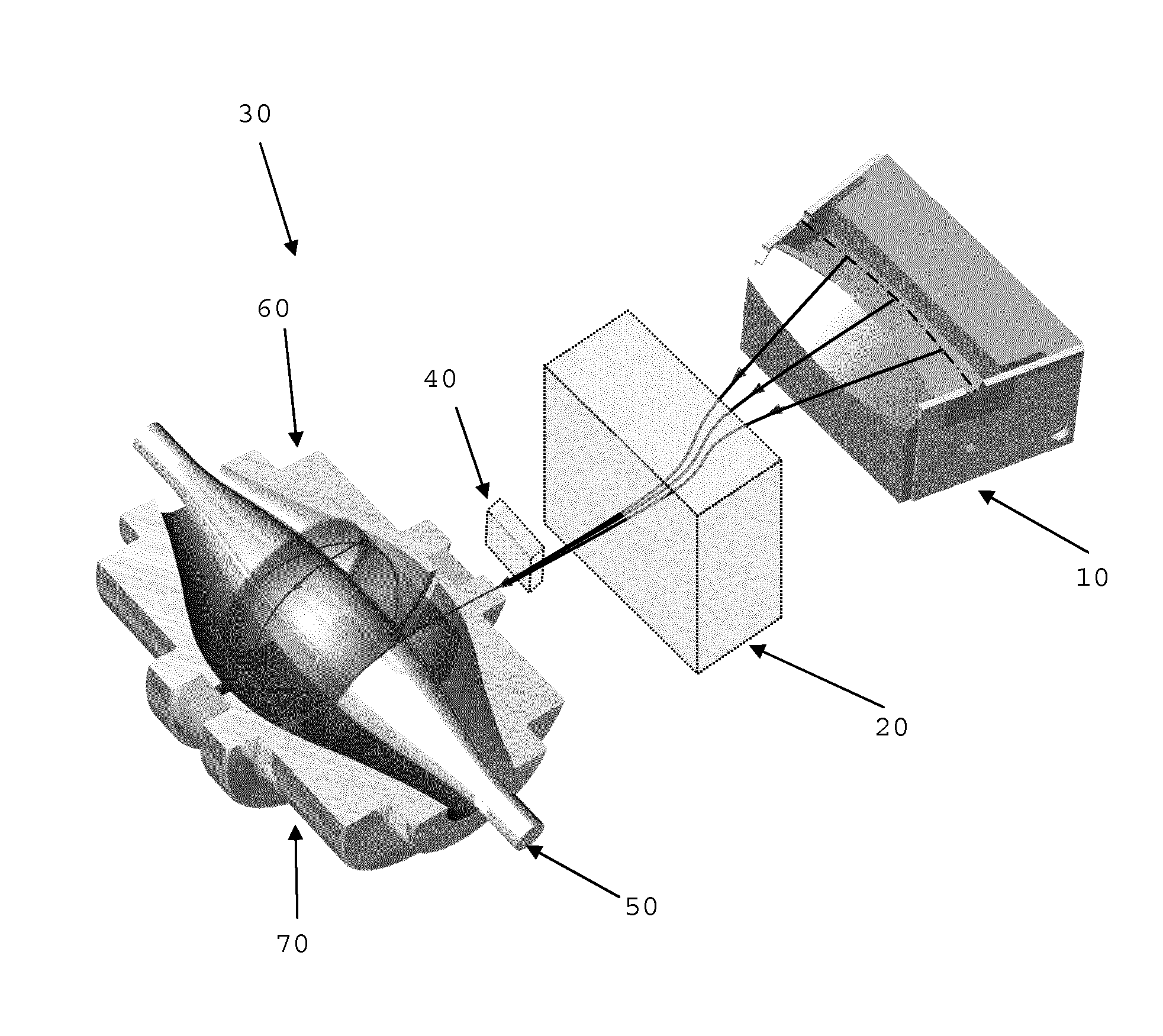
[0037]Referring first to FIG. 1, there is shown schematically a part of an existing mass spectrometer. The part of the mass spectrometer comprises: an ion storage device 10; ion optics 20; and a mass analyser 30. The mass analyser 30 is of Orbitrap-type and comprises: a deflector 40; a central electrode 50; a first outer electrode 60; and a second outer electrode 70 (the outer electrodes 60, 70 radially enclose the central electrode 50 and are shown cut-away in the Figure to reveal the central electrode for illustration). The general operation of such a mass analyser is well known, but further details may be found in WO-A-02 / 078046, WO-A-2006 / 129109 and WO-A-2007 / 000587, the contents of which are incorporated by reference herein.

[0038]Ion injection into the mass analyser 30 is implemented by the following steps. Firstly, ions coming from an external ion source are stored in the ion storage device 10 (preferably a curved trap, C-trap, for example as described in U.S. Pat. No. 7,498,5...


PUM

PropertyMeasurementUnit
molecular weightaaaaaaaaaa

Abstract

A mass analyzer comprises: an electrical field generator, providing a time-varying electric field for injection of ions to be analyzed, excitation of ions to be analyzed or both; first and second detection electrodes, each of which receives a respective voltage pickup due to the time-varying electric field and provides a respective detection signal based on a respective image current at the detection electrode; and a differential amplifier, providing an output based on the difference between the detection signal for the first detection electrode and the detection signal for the second detection electrode. It may also be provided that the electrical field generator comprises at least one field generating electrode without a spatially symmetrical counterpart and the capacitance between each field generating electrode and the first detection electrode is substantially the same as the capacitance between that field generating electrode and the second detection electrode.

Description

TECHNICAL FIELD OF THE INVENTION[0001]The present invention relates to a mass analyser, a mass spectrometer comprising such a mass analyser, a method of mass analysis and a method of manufacturing a mass analyser.BACKGROUND TO THE INVENTION[0002]Fourier Transform Mass spectrometry (FTMS) can be used in Life Sciences for analysis of peptides, proteins and other heavy biological molecules. However, specific problems arise in FTMS in the analysis of heavy protein ions. These problems may also arise with other heavy biological molecule ions but protein ions will be referred to herein for illustration. Accordingly, the invention is not limited in application to analysis of proteins. A wide isotopic distribution of heavy protein ions results in a unique interference effect observed in FTMS. Initial constructive interference between the ion oscillations is quickly followed by destructive interference, when practically no signal is detected from those ions. This effect is discussed in Hofst...

Claims


Application Information

Patent Timeline
Patent Type & Authority Patents(United States)
IPC IPC(8): H01J49/00B01D59/44H01J49/26
CPCH01J49/26H01J49/425Y10T29/49117H01J49/027H01J49/4245
Inventor DENISOV, EDUARD V.KHOLOMEEV, ALEXANDERHAUSCHILD, JAN-PETERMAKAROV, ALEXANDER A.
Owner THERMO FISHER SCI BREMEN