Reactive power compensation in electrical power system

a technology of reactive power compensation and electrical power system, applied in the field of reactive power compensation system in electrical power system, can solve problems such as power system voltage and frequency stability problems, power transmission grid variation, and difficult integration with power transmission grids, so as to improve fault tolerance and redundancy, and effectively manage the reactive power compensation requirements

Active Publication Date: 2014-09-30
GAMESA INNOVATION & TECH SA
View PDF11 Cites 9 Cited by
  • Summary
  • Abstract
  • Description
  • Claims
  • Application Information

AI Technical Summary

Benefits of technology

[0011]Another objective of the present invention is to effectively eliminate current harmonics in the electrical power system.
[0012]Still another objective of the present invention is to implement an improved control strategy of the reactive power compensation system eliminate current harmonics in the electrical power system.
[0015]Various embodiments of the present invention offer several advantages. The present invention implements a modular design of the reactive power compensation system. The reactive power compensation system is operated in accordance with a sequential control mechanism. The present invention not only effectively manages the reactive power compensation requirements in the electrical power system but also effectively eliminates the current harmonics up to 19th order harmonics under varying load conditions. Further, as a consequence of the modular design, the present invention provides improved fault tolerance and redundancy in the reactive power compensation system.

Problems solved by technology

However, as a consequence of uncertainty of output in wind energy based power generation units, the integration with power transmission grids becomes a challenging task.
One of the main problems associated with wind farms is the variation of power supply due to the intermittent nature of the blowing winds.
The non-uniform production of power leads to problems in power system voltage and frequency stability.
Thus, an important challenge is to implement such solutions that facilitate integration of distributed wind energy based electrical power generation units with power transmission grids while maintaining power quality as well as power system stability.
Thus, an important challenge in electric power transmission is to control the reactive power and keep the power factor as close to unity as possible.
However, this technique suffers from drawbacks of fluctuating current characteristics under low voltage situations.
However, these control approaches fail to satisfactorily implement an effective reactive power compensation and harmonics elimination solution.
Moreover, currently known STATCOM implementations suffer from drawbacks arising due to a monolithic design.
However, under certain conditions, significant magnitude of low-order harmonic currents is generated in the electrical power system and accordingly, the power generation unit experiences a non-sinusoidal load, which affects the stability of the electrical power system.
The presence of current harmonics affects power quality and power system stability.
However, if the current harmonics spectrum changes, the passive filters are not able to effectively attenuate the current harmonics.
However, operation of sensitive power electronics based devices used in a wind farm are adversely affected by the FACTS system operating close to the wind farm.
This may potentially lead to high current distortions, which leads to windmill trips and production losses.
Accordingly, use of FACTS based current harmonics elimination systems near wind farms is a challenging task.

Method used


Image

  • Reactive power compensation in electrical power system
  • Reactive power compensation in electrical power system
  • Reactive power compensation in electrical power system

Examples


Embodiment Construction

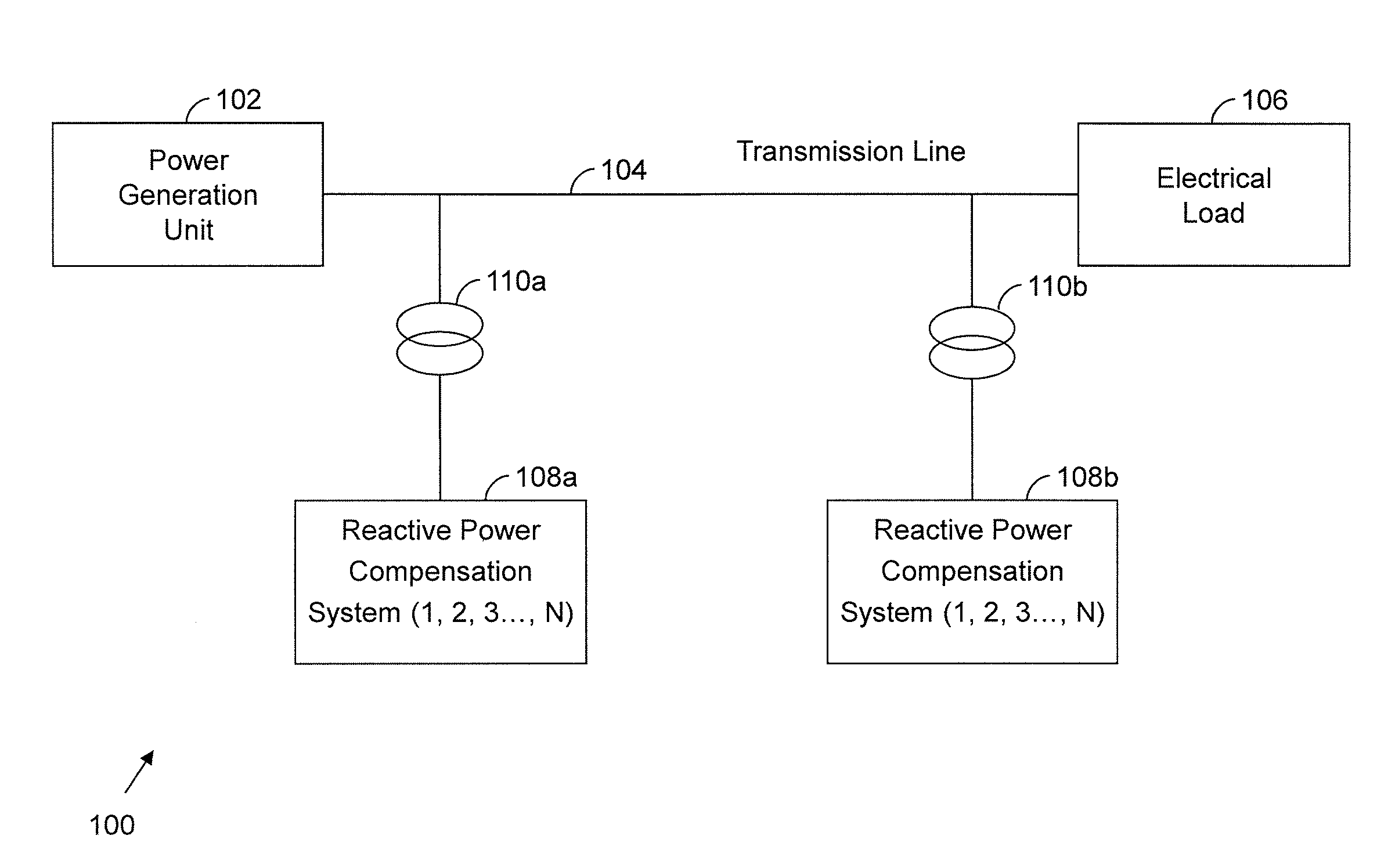
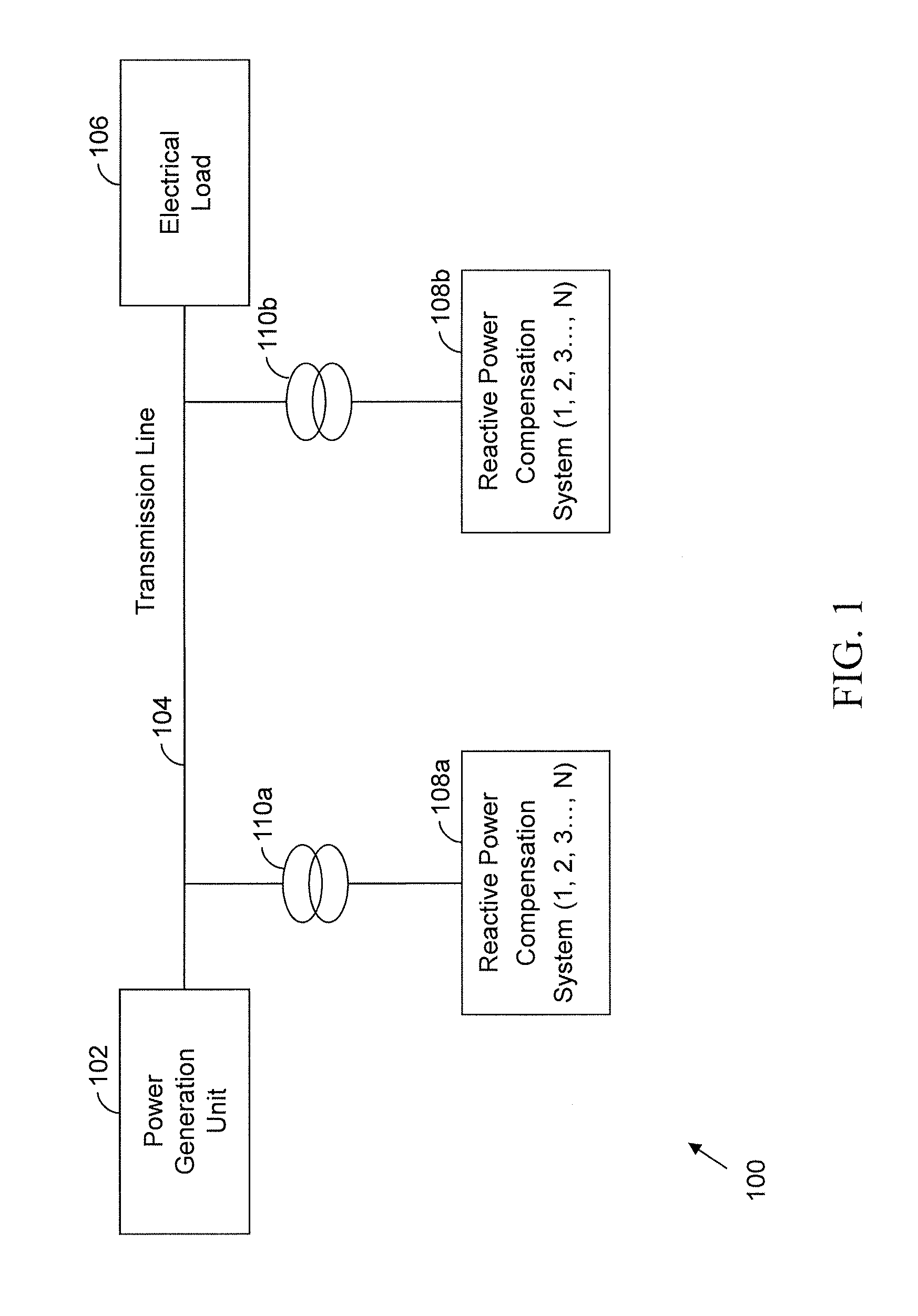
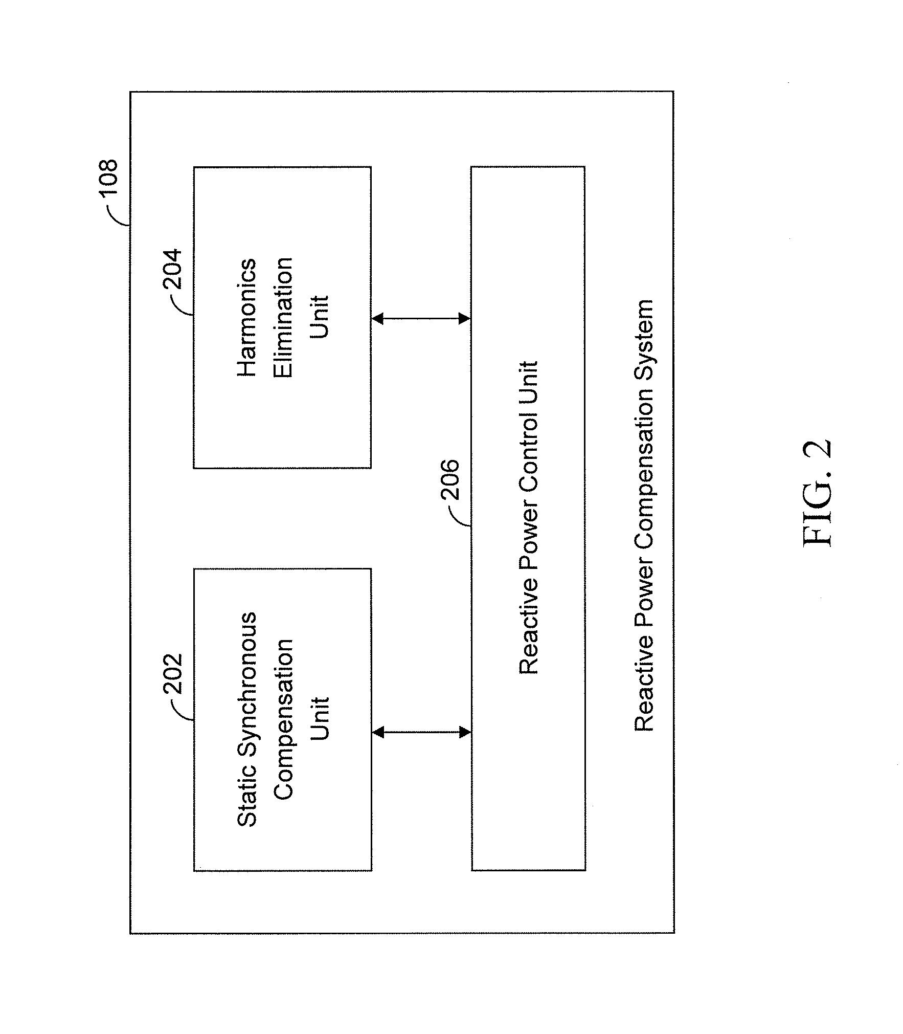
[0026]Before describing in detail the system for reactive power compensation in an electrical power system, in accordance with various embodiments of the present invention, it should be observed that the present invention resides primarily in combinations of system elements related to reactive power compensation in an electrical power system. Accordingly, the apparatus components have been represented, where appropriate, by conventional symbols in the drawings, showing only those specific details that are pertinent for an understanding of the present invention, so as not to obscure the disclosure with details that will be readily apparent to those with ordinary skill in the art, having the benefit of the description herein.

[0027]In this document, the terms “comprises,”“comprising,” or any other variation thereof, are intended to cover a non-exclusive inclusion, such that a process, method, article or apparatus that comprises a list of elements does not include only those elements bu...


PUM


Abstract

A reactive power compensation system for compensating reactive power requirements in an electrical power system. The reactive power compensation system includes a static synchronous compensation unit, a current harmonics elimination unit, and a compensation control unit. The static synchronous compensation unit includes a plurality of static synchronous compensation modules for compensating reactive power in the electrical power system. The current harmonics elimination unit includes a plurality of active filter modules for eliminating current harmonics generated in the electrical power system. The compensation control unit implements a sequential control mechanism for regulating the operation of the static synchronous compensation modules and the active filter modules.

Description

RELATED APPLICATION INFORMATION[0001]This application is a 371 of International Application PCT / ES2009 / 070316 filed 27 Jul. 2009 and entitled “REACTIVE POWER COMPENSATION IN ELECTRICAL POWER SYSTEM”, which was published on 3 Feb. 2011, with International Publication Number WO 2011 / 012733 A1.FIELD OF THE PRESENT INVENTION[0002]The present invention relates, in general, to the field of electrical power systems, and specifically, to a system for reactive power compensation in an electrical power system. More specifically, the present invention relates to a system for reactive power compensation in an electrical power system including a wind power generation unit.BACKGROUND OF THE PRESENT INVENTION[0003]With the energy crisis engulfing the world, alternative methods of energy generation are becoming increasingly important. Wind energy has emerged as a promising renewable energy source. The use of wind farms to generate energy is becoming increasingly popular in developed as well as deve...

Claims


Application Information

Patent Timeline
Patent Type & Authority Patents(United States)
IPC IPC(8): G05F5/00H02M1/12H02J3/01H02J3/18H02J3/20
CPCH02J3/1842H02J3/20Y02E40/16H02J3/01Y02E40/22Y02E40/40Y02E40/10Y02E40/20Y02E40/30
Inventor AGUDO, ARAQUE, ANDRES
Owner GAMESA INNOVATION & TECH SA
Why Eureka
Try Eureka