Correction method for differential phase contrast imaging

a correction method and imaging technology, applied in imaging devices, instruments, applications, etc., can solve problems such as aggravated problems, offset errors of 2, and 2 phase wrapping, and achieve the effect of enhancing the image quality of acquired x-ray images and better estimation of correction offsets

Active Publication Date: 2014-10-07
KONINK PHILIPS ELECTRONICS NV
View PDF4 Cites 68 Cited by
  • Summary
  • Abstract
  • Description
  • Claims
  • Application Information

AI Technical Summary

Benefits of technology

[0025]A second exemplary embodiment of the present application is directed to a method for reducing the influence of induced phase errors on the image quality of an interferometer setup for imaging an object by means of electromagnetic waves or matter waves, wherein the object causes an altered phase information of the electromagnetic waves or matter waves according to a local refraction index. As described above with reference to the first exemplary embodiment of the invention, said interferometer setup comprises a radiation source for emitting the emitting electromagnetic waves or matter waves transmitting said object, a radiation detector for detecting these electromagnetic waves or matter waves and a processing means for gaining information representative of the object's local phase gradient in at least one transverse direction perpendicular to the interferometer setup's optical axis. According to the present invention, said method comprises the steps of determining the pixel positions of noisy pixels and / or determining at which pixel positions of a detected phase gradient image the local phase gradient exceeds a predefined threshold value and marking all these pixels as “bad”, performing a line integration over the local phase gradient, thus yielding an integrated phase gradient image, analyzing the integrated phase gradient image for characteristic line artifacts occurring behind pixels of strong phase gradient which have been marked as “bad” and introducing a correction phase offset of 2π radians or an integer multiple thereof at the position of each “bad” pixel if analysis shows that a measured 2π phase offset error or an integer multiple thereof between immediately adjacent line artifacts which is induced by said line integration persists after passing a pixel that has been marked as “bad” so as to compensate this 2π phase offset error or an integer multiple thereof. Preferably, it may be intended that this method is used for reducing the influence of induced phase errors on the image quality of a DPCI-based grating interferometer setup of the Talbot-Lau type for hard X-ray phase contrast imaging.
[0028]A third exemplary embodiment of the present application is dedicated to the use of a method as described with reference to the second exemplary embodiment in the scope of a medical X-ray radiography, 3D rotational angiography or computed tomography application scenario for enhancing the image quality of acquired X-ray images.

Problems solved by technology

One major drawback of DPCI is 2π phase-wrapping, which may occur if the phase between two adjacent pixels (given in radians) varies by more than π. In this case, an offset error of 2π is induced after integration of the differential phase along a line as described by C. Kottler et al. in Optics Express 15 (3), p.
This problem is aggravated by noise in the DPCI images.
However, this approach is problematic for medical imaging, which is because a rotation of the setup during the clinical procedure is mechanically challenging as regards mechanical tolerances and precision accuracy.
Furthermore, it requires a double exposure of the patient with X-rays, which is not acceptable for dose reasons.

Method used


Image

  • Correction method for differential phase contrast imaging
  • Correction method for differential phase contrast imaging
  • Correction method for differential phase contrast imaging

Examples


Embodiment Construction

[0045]In the following sections, an exemplary embodiment of the claimed DPCI setup according to the present invention will be explained in more detail referring to the accompanying drawings and starting with a brief description of the relevant prior art.

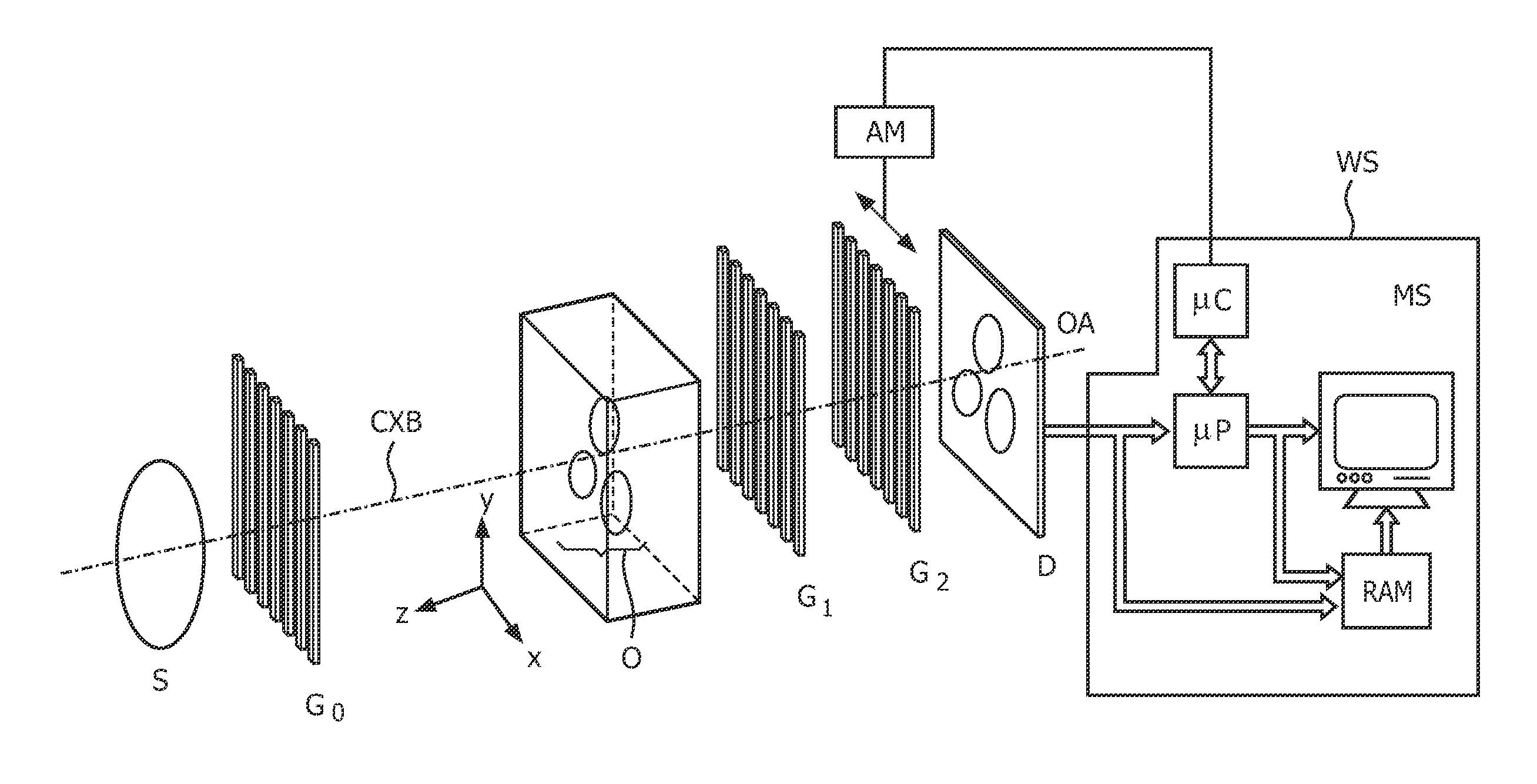
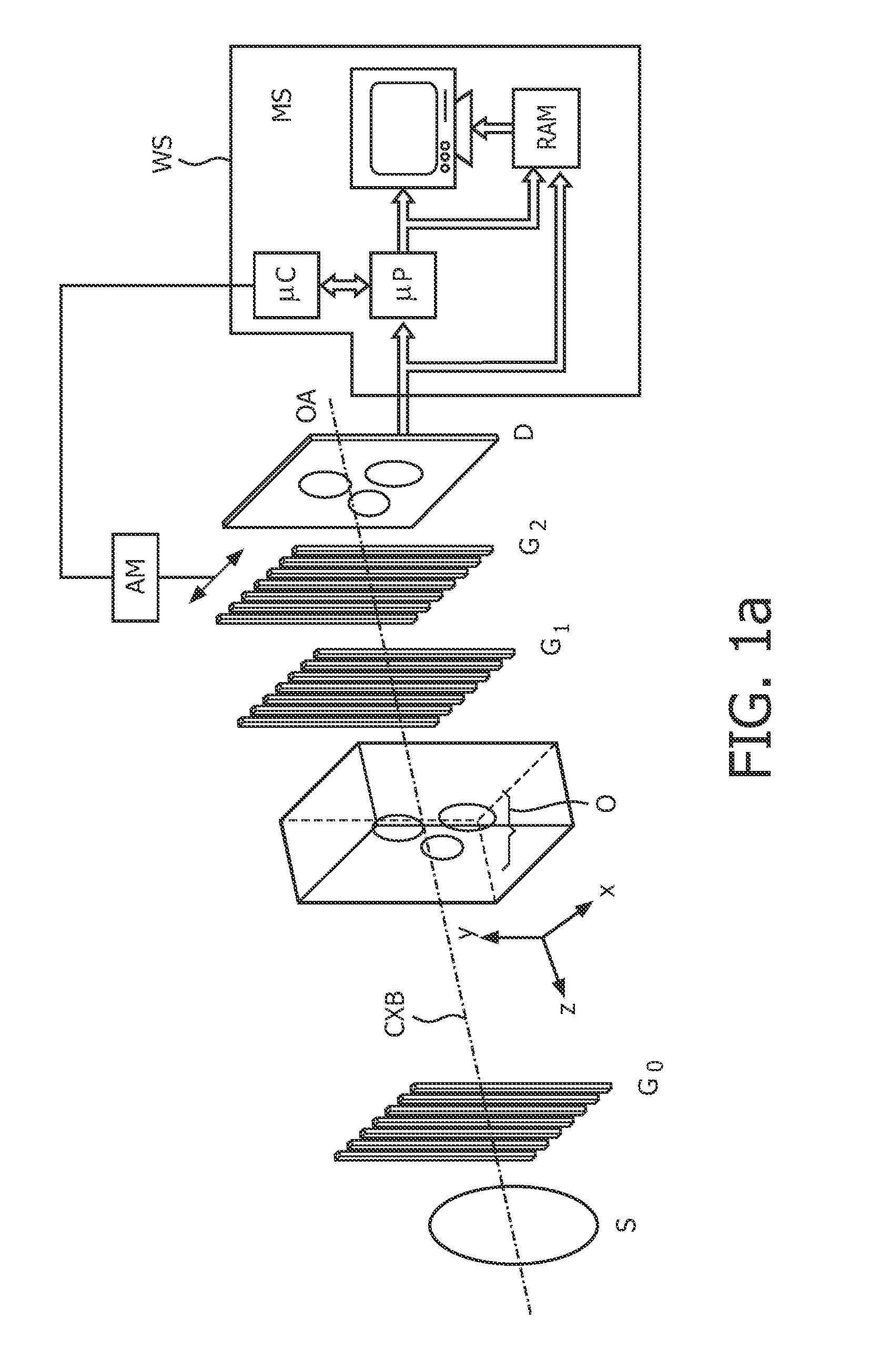
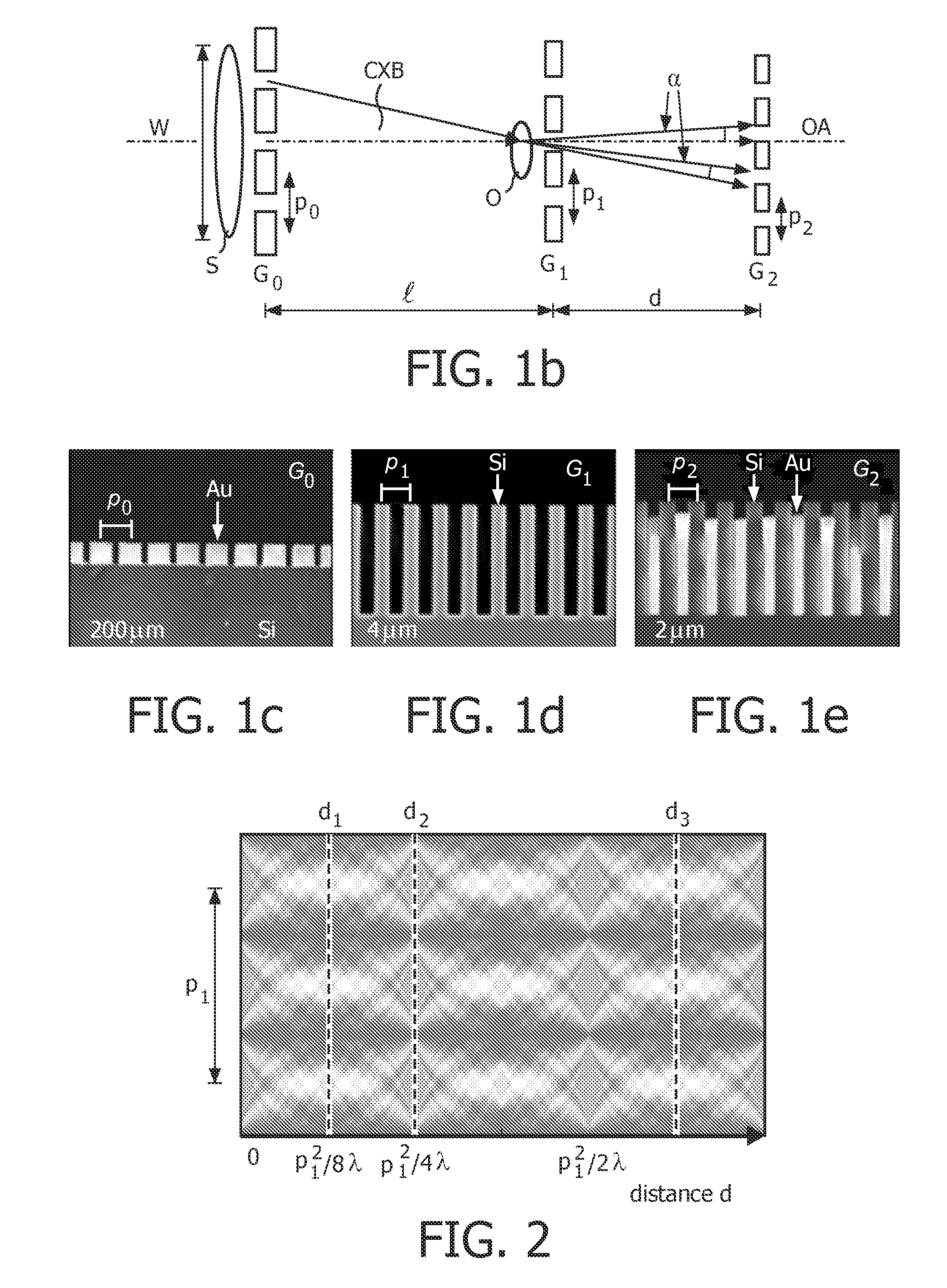
[0046]The experimental DPCI grating interferometer setup for a Talbot-Lau type hard-X-ray imaging interferometer as known from Pfeiffer and Weitkamp is shown in FIGS. 1a and 1b. Using this kind of interferometer leads to the effect that interfering X-ray beams are not completely separated but merely sheared by a small angle so that they pass through different, closely spaced parts of the sample. The hard-X-ray imaging interferometer of Pfeiffer and Weitkamp comprises an incoherent X-ray source S, a source grating G0 for achieving spatial beam coherence, a diffractive grating G1 (herein also referred to as phase grating) having a plurality of equidistant X-ray absorbing strips extending in parallel in a direction normal to the interfe...


PUM

PropertyMeasurementUnit
temporal coherence lengthsaaaaaaaaaa
temporal coherence length ξtaaaaaaaaaa
spatial coherence lengthaaaaaaaaaa

Abstract

The present invention generally refers to a correction method for grating-based X-ray differential phase contrast imaging (DPCI) as well as to an apparatus which can advantageously be applied in X-ray radiography and tomography for hard X-ray DPCI of a sample object or an anatomical region of interest to be scanned. More precisely, the proposed invention provides a suitable approach that helps to enhance the image quality of an acquired X-ray image which is affected by phase wrapping, e.g. in the resulting Moiré interference pattern of an emitted X-ray beam in the detector plane of a Talbot-Lau type interferometer after diffracting said X-ray beam at a phase-shifting beam splitter grating. This problem, which is further aggravated by noise in the obtained DPCI images, occurs if the phase between two adjacent pixels in the detected X-ray image varies by more than π radians and is effected by a line integration over the object's local phase gradient, which induces a phase offset error of π radians that leads to prominent line artifacts parallel to the direction of said line integration.

Description

FIELD OF THE INVENTION[0001]The present invention generally refers to a correction method for grating-based X-ray differential phase contrast imaging (DPCI) as well as to an apparatus which can advantageously be applied in X-ray radiography and tomography for hard X-ray DPCI of a sample object or an anatomical region of interest to be scanned. More precisely, the proposed invention provides a suitable approach that helps to enhance the image quality of an acquired X-ray image which is affected by phase wrapping, e.g. in the resulting Moiré interference pattern of an emitted X-ray beam in the detector plane of a Talbot-Lau type interferometer after diffracting said X-ray beam at a phase-shifting beam splitter grating. This problem, which is further aggravated by noise in the obtained DPCI images, occurs if the phase between two adjacent pixels in the detected X-ray image varies by more than π radians and is effected by a line integration over the object's local phase gradient, which ...

Claims


Application Information

Patent Timeline
Patent Type & Authority Patents(United States)
IPC IPC(8): G03H5/00A61B6/00G01N23/04G21K1/06
CPCA61B6/00A61B6/484G01N23/04G21K1/06A61B6/4291G21K2207/005A61B6/4092G01N23/041
Inventor ENGEL, KLAUS JUERGENGELLER, DIETERVOGTMEIER, GEREON
Owner KONINK PHILIPS ELECTRONICS NV
Why Eureka
Try Eureka