Temporary ostomy appliance
a technology of ostomy and ostomy, which is applied in the field of temporary ostomy equipment, can solve the problems of high morbidity and mortality, high cost of two such serious operations, and the inability to use temporary ileostomy as extensively, and achieves the effect of minimizing the pressure on the inside of the balloon and minimizing the potential harmful pressure on mucosal tissu
- Summary
- Abstract
- Description
- Claims
- Application Information
AI Technical Summary
Benefits of technology
Problems solved by technology
Method used
Image
Examples
first embodiment
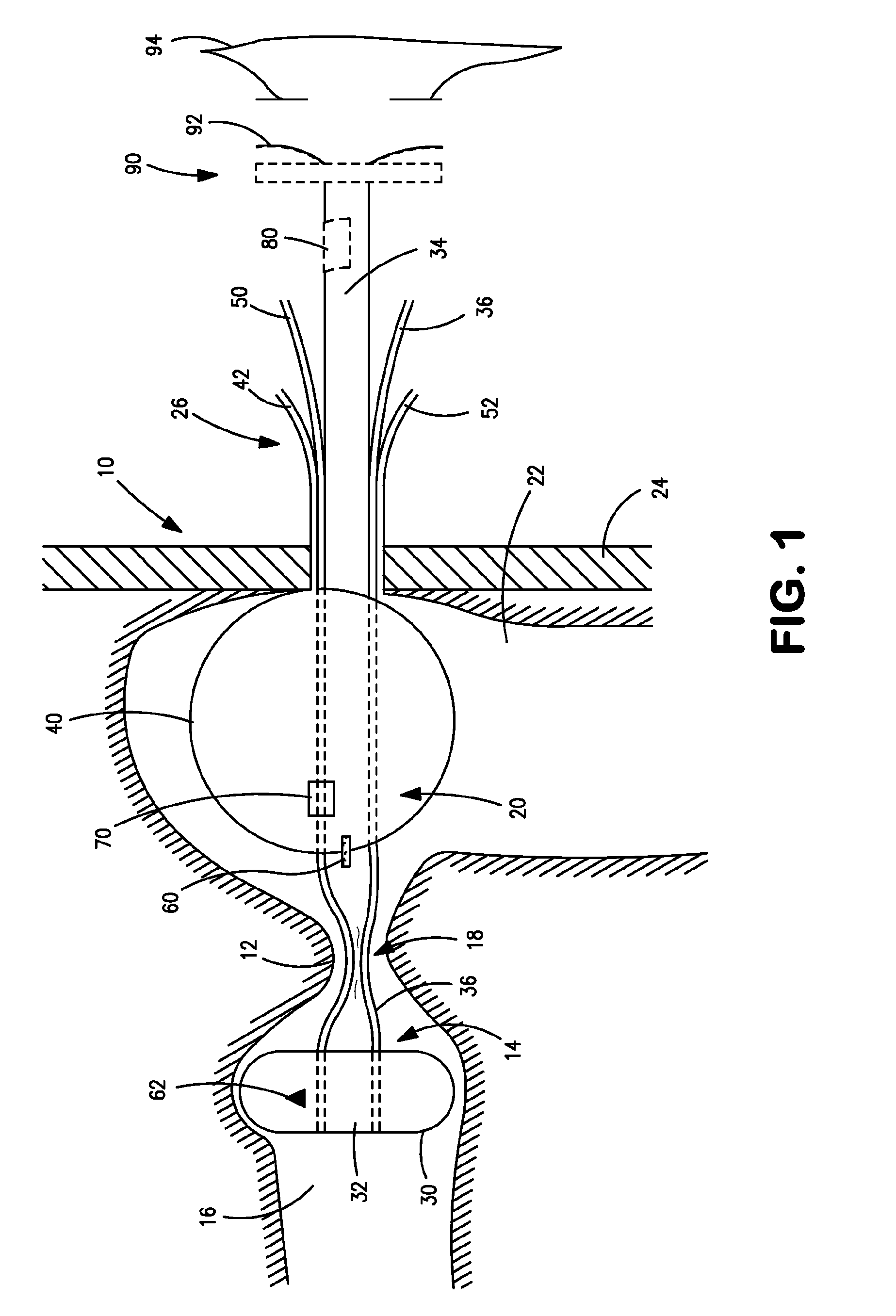
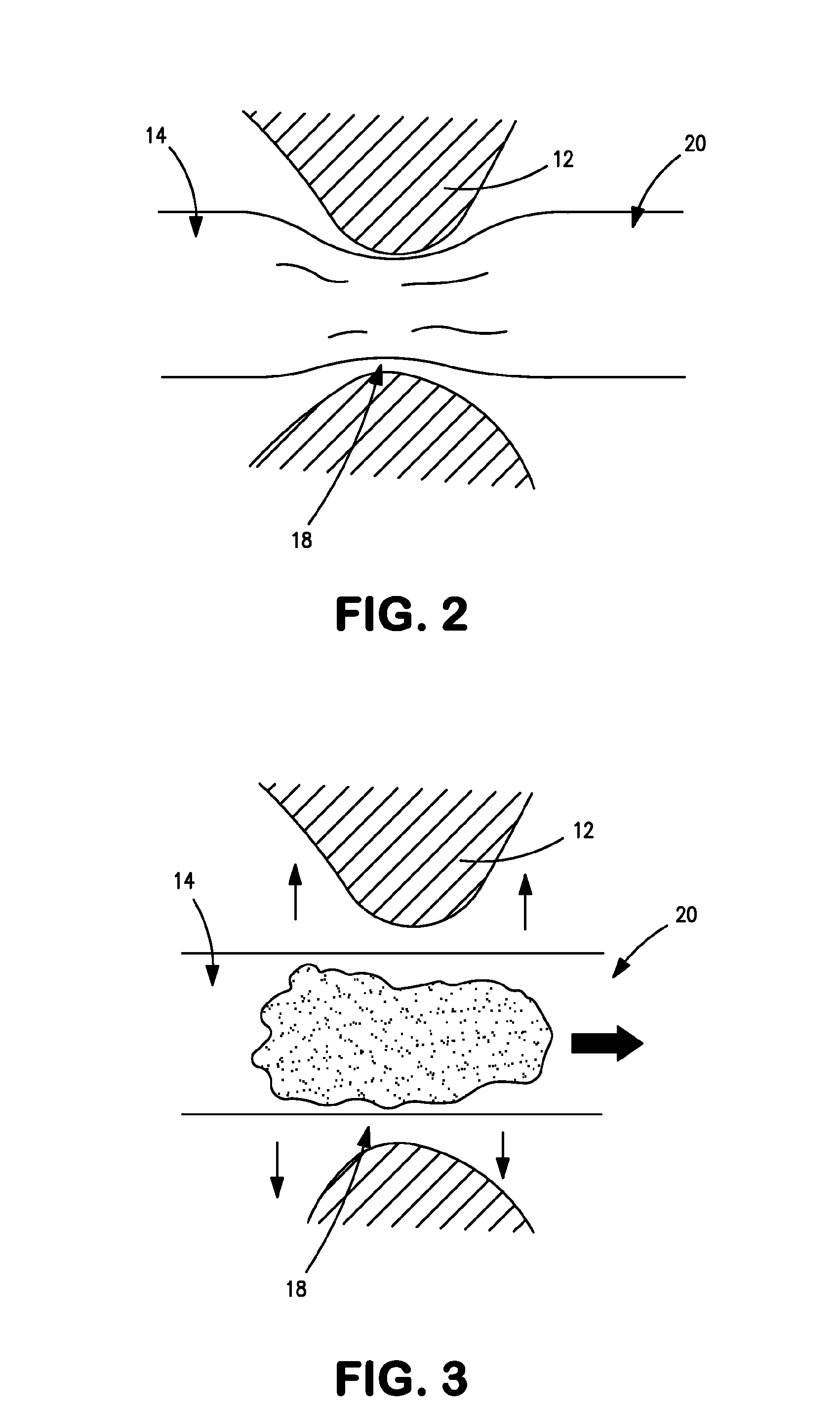
[0021]Referring to FIG. 1, temporary ostomy appliance is a transcecal ileostomy appliance comprising a catheter 10 intended for insertion through the cecal valve 12 of the intestine. The catheter 10 includes a first distal portion 14 intended to be received in the ileum 16, a second portion 18 intended to sit at the cecal valve 12, a third portion 20 intended to be received in the large intestine 22, a fourth portion 25 intended to pass through the abdominal wall 24, and a fifth proximal portion 26 intended to extend outside the body. The catheter 10 is made of any suitable material including, for example, silicone and / or polyurethane.
[0022]An inflatable blocking balloon or cuff 30 is optionally provided at the first distal portion 14 for obstructing the ileum 16, and causing effluent to be diverted through an aperture 32 into a drainage lumen 34 of the catheter 10. A blocking balloon inflation lumen 36 communicates with the blocking balloon 30 for inflation and deflation of the blo...
second embodiment
[0043]The balloon 40 may be supplemented by the removable bridge features 102 of the second embodiment, and this removable fastening may render the transcecal portion 110 of the catheter 10 unnecessary if the balloon 40 is sufficiently anchored, by the removable bridge features 102 or other means, against unwanted turning in the large intestine 22. If the transcecal portion 110 is implemented, the transcecal portion 110 may also include one or more removable bridge features 102. Such a releasable fastening may supplement the balloon 30, or the balloon 30 may be omitted from the transcecal portion 110.
third embodiment
[0044]The temporary ostomy appliance of the third embodiment may be removed without surgery in a similar manner to the first (and / or second) embodiment. The fixation balloon 40 is deflated, and the blocking balloon 30 (if implemented) is also deflated. This allows easy withdrawal of the catheter 10 without additional surgery.
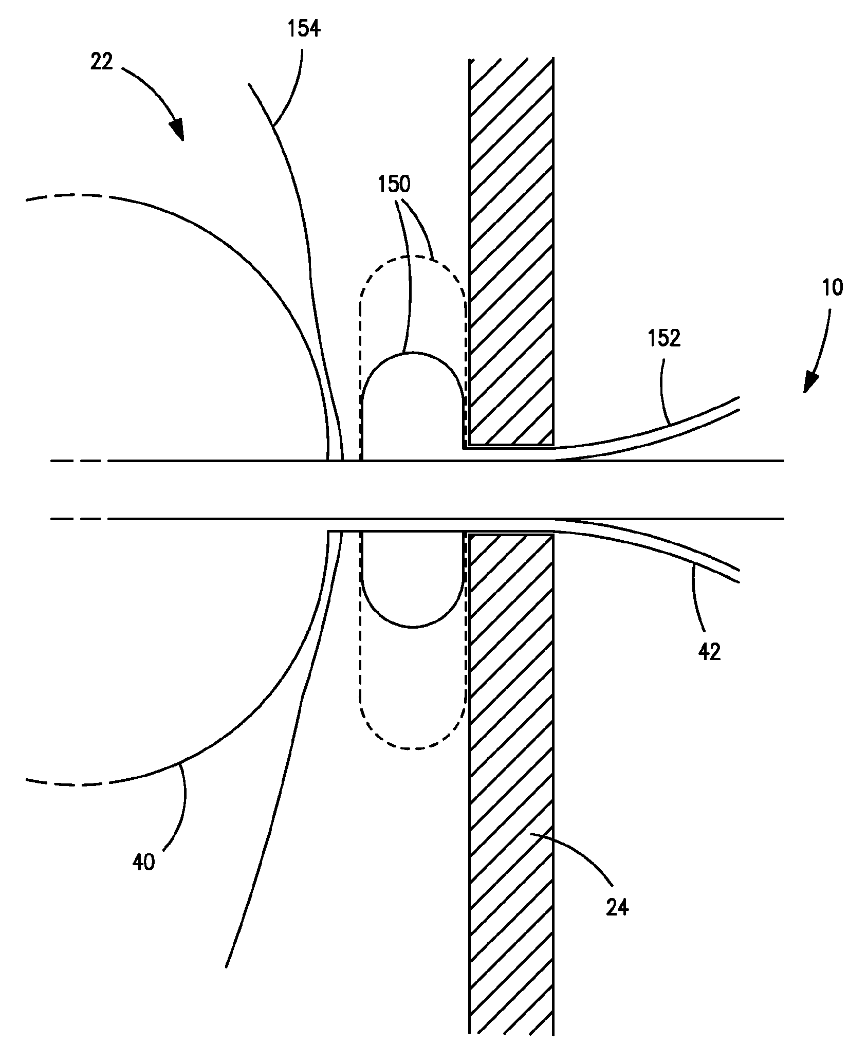
[0045]Referring to FIG. 8, a fourth embodiment of temporary ostomy appliance is illustrated. The fourth embodiment may be used independently, or it may be combined with any of the features of any of the preceding embodiments. Whereas in the first-third embodiments, the appliance generally draws the large intestine 22 directly up against the abdominal wall 24 at the site where the catheter 10 passes through the abdominal wall 24 and / or enters the large intestine 22, in the present embodiment, a fender 150 is provided to separate and / or cushion the outside surface of the wall 154 of the large intestine 22 from direct contact with the abdominal wall 24. The fender ...
PUM
 Abstract
Description
Claims
Application Information
 - R&D
- Intellectual Property
- Life Sciences
- Materials
- Tech Scout
- Unparalleled Data Quality
- Higher Quality Content
- 60% Fewer Hallucinations
Browse by: Latest US Patents, China's latest patents, Technical Efficacy Thesaurus, Application Domain, Technology Topic, Popular Technical Reports.
© 2025 PatSnap. All rights reserved.Legal|Privacy policy|Modern Slavery Act Transparency Statement|Sitemap|About US| Contact US: help@patsnap.com


