Minimal thickness synthetic antiferromagnetic (SAF) structure with perpendicular magnetic anisotropy for STT-MRAM

a synthetic antiferromagnetic and perpendicular magnetic anisotropy technology, applied in the field of magnetoresistive random access memory (mram), can solve the problems of undesirable asymmetry, difficult to achieve ho=0 in practice, and difficult to use external magnetic fields generated by current carrying lines to switch the magnetic moment direction. to achieve the effect of enhancing the tmr ratio in the mtj

Active Publication Date: 2014-10-14
TAIWAN SEMICON MFG CO LTD
View PDF12 Cites 97 Cited by
  • Summary
  • Abstract
  • Description
  • Claims
  • Application Information

AI Technical Summary

Benefits of technology

[0013]Alternatively, the laminated AP2 structure may be replaced by a L10 ordered alloy of the form MT wherein M is Rh, Pd, Pt, Ir, or an alloy thereof, and T is Fe, Co, Ni or alloy thereof. Furthermore, the MT alloy may be doped with B to give a boron content up to 40 atomic %. In yet another embodiment, the AP2 layer may be an amorphous rare earth-transition (RE-TM) alloy such as TbCo, TbFeCo, or GdFeCo that exhibits PMA. A tunnel barrier comprised of MgO or another metal oxide formed on a top surface of the SAF structure helps to maintain PMA character within the thin CoFeB layer. There is a free layer contacting a top surface of the tunnel barrier and a cap layer as the uppermost layer in the MTJ stack. Preferably, the free layer has PMA to enhance the TMR ratio in the MTJ.

Problems solved by technology

As the size of MRAM cells decreases, the use of external magnetic fields generated by current carrying lines to switch the magnetic moment direction becomes problematic.
As a result, spin valve structures based on PMA are capable of scaling for higher packing density which is one of the key challenges for future MRAM applications and other spintronic devices.
This asymmetry is undesirable since for a given free layer coercivity (Hc), Ho should be zero for optimum stability.
Generally, Ho=0 is difficult to achieve in practice, and as a rule, Ho<15% of Hc is a reasonable target in actual devices.

Method used


Image

  • Minimal thickness synthetic antiferromagnetic (SAF) structure with perpendicular magnetic anisotropy for STT-MRAM
  • Minimal thickness synthetic antiferromagnetic (SAF) structure with perpendicular magnetic anisotropy for STT-MRAM
  • Minimal thickness synthetic antiferromagnetic (SAF) structure with perpendicular magnetic anisotropy for STT-MRAM

Examples


example 1

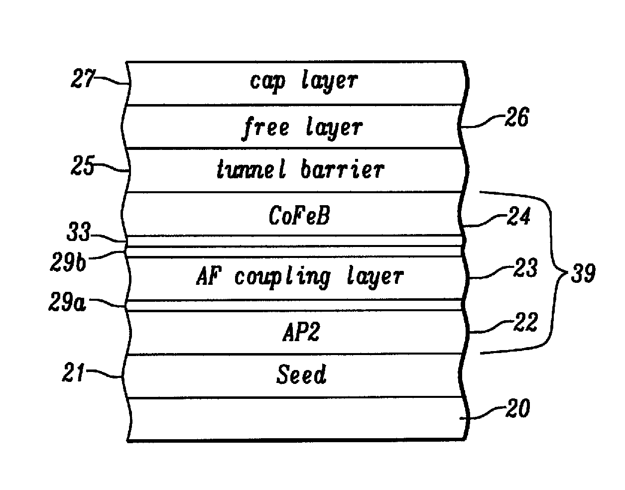
[0051]To further describe the effect of AP2 layer thickness on SAF reference layer properties with regard to the second embodiment that has an AP2 / Co / Ru / Co / CoFeB configuration, a MTJ stack was fabricated with the following bottom spin valve configuration where the number following the layer indicates the layer thickness: TaN20 / Mg7 / NiCr50 / (Cu2.5 / Ni6)10 / Co4 / Ru4 / Co4 / Co20Fe60B2010 / MgO(8 / 4ROX) / Co20Fe60B203 / Ta20 / Ru50. In this case, TaN / Mg / NiCr is the seed layer and Ta / Ru serves as a cap layer. The MgO tunnel barrier is made by first depositing an 8 Angstrom thick Mg layer, followed by an ROX process, and then depositing a second Mg layer that is 4 Angstroms thick. Ho is measured to be −190 Oe and the Mst balance ratio=0.40. If the number of laminates “n” in the (Co / Ni)n AP2 stack is reduced from 10 to 6, then Ho=0 and the balance ratio=0.66. When n is lowered to 4, then Ho=125 Oe and the balance ratio=0.99.

[0052]Referring to FIG. 11, the viability of a SAF reference layer according to the...


PUM


Abstract

A synthetic antiferromagnetic (SAF) structure for a spintronic device is disclosed and has an AP2 / antiferromagnetic (AF) coupling / CoFeB configuration. The SAF structure is thinned to reduce the fringing (Ho) field while maintaining high coercivity. The AP2 reference layer has intrinsic perpendicular magnetic anisotropy (PMA) and induces PMA in a thin CoFeB layer through AF coupling. In one embodiment, AF coupling is improved by inserting a Co dusting layer on top and bottom surfaces of a Ru AF coupling layer. When AP2 is (Co / Ni)4, and CoFeB thickness is 7.5 Angstroms, Ho is reduced to 125 Oe, Hc is 1000 Oe, and a balanced saturation magnetization-thickness product (Mst)=0.99 is achieved. The SAF structure may also be represented as FL2 / AF coupling / CoFeB where FL2 is a ferromagnetic layer with intrinsic PMA.

Description

RELATED PATENT APPLICATION[0001]This application is related to U.S. Pat. No. 8,064,244 which is herein incorporated by reference in its entirety.TECHNICAL FIELD[0002]The present disclosure relates to a Magnetoresistive Random Access Memory (MRAM) that includes a magnetic tunnel junction (MTJ) in which a composite reference layer has antiferromagnetic coupling between a layer with intrinsic perpendicular magnetic anisotropy (PMA) and a CoFeB layer to establish PMA in the latter, and composite reference layer thickness is reduced to minimize the stray field (Ho) on the free layer.BACKGROUND[0003]Magnetoresistive Random Access Memory (MRAM), based on the integration of silicon CMOS with MTJ technology, is a major emerging technology that is highly competitive with existing semiconductor memories such as SRAM, DRAM, and Flash. Similarly, spin-transfer (spin torque or STT) magnetization switching described by C. Slonczewski in “Current driven excitation of magnetic multilayers”, J. Magn....

Claims


Application Information

Patent Timeline
Patent Type & Authority Patents(United States)
IPC IPC(8): H01L29/82
CPCH01F10/3272H01F41/307H01L43/10H01L43/02H01F38/00H01F10/3286H01F10/123H01L29/82H10N50/10H10N50/85G11C11/161H10B61/00H10B61/10H10N50/80
Inventor BEACH, ROBERTJAN, GUENOLEWANG, YU-JENTONG, RU-YING
Owner TAIWAN SEMICON MFG CO LTD
Why Eureka
Try Eureka