Clog indicating device in a dust collector

a technology of indicating device and dust collector, which is applied in the direction of auxillary pretreatment, instruments, separation processes, etc., can solve the problems of operator falling, affecting the collection efficiency of filters, and slippery floor of the shop

Inactive Publication Date: 2014-10-21
AOI SEIKO
View PDF8 Cites 3 Cited by
  • Summary
  • Abstract
  • Description
  • Claims
  • Application Information

AI Technical Summary

Benefits of technology

[0012]An object of the present invention is to provide a clog indicating device in a dust collector that has a simple structure and is capable of indicating in an easily viewable fashion. The object of the invention will be achieved by a following clog indicating device in a dust collector:
[0014]With this invention, the clog indicating device is easily constructed by locating the indicating float and cover member at the exhaust port of the dust collector, and the clog indicating device is capable of indicating clogging of dust collecting filters in an easily viewable fashion by the colored indicating float, at low cost. Further, since the device of the invention does not require any sensors or detecting circuit, it can be manufactured inexpensively, does not require maintenance and inspection, and rarely goes out of order.
[0017]Furthermore, it is desired that the indicating float is fabricated of foamed synthetic resin or of a hollow synthetic resin body so as to be light. This configuration will make pressure loss in the exhausted air from the dust collector minimum.

Problems solved by technology

In a shop doing machine work, machine tools generate dust laden oil mist or the like.
If left untreated, the oil mist not only makes working environment of the shop worse by causing bad odor in the shop, intrusion of the dust laden fluid into equipment and its control panels and dirt of walls, but also makes the floor of the shop slippery, which may cause fall of operators.
As the dust collecting filter collects the dust laden fluid, it is clogged due to collected dust laden fluid, which turns down collection efficiency of the filter and lets uncollected dust laden fluid released in the shop, thus making the working environment worse as described above.
This must be solved by frequent maintenance and inspection of the dust collecting filters, but it is difficult for a busy shop worker to watch the filters all of the time and clean or replace the filters as soon as they are clogged.
However, in addition to electric sensing by the pressure sensor, the above conventional clog monitoring device also uses a temperature sensor for monitoring clogging of the filter.
Since the device monitors clogging by means of a temperature signal as well as a pressure detection signal, the device has a complicated structure with the sensors and their detection circuits, and costs a lot of money for manufacturing.
Further, the device requires maintenance and inspection for the sensors and detection circuits.
However, although the index needle is mounted on a lateral of the exhaust port of the dust collector, the needle is very thin and is not easily viewable in a large shop, therefore it is not easy for operators to notice of clogging.

Method used


Image

  • Clog indicating device in a dust collector
  • Clog indicating device in a dust collector
  • Clog indicating device in a dust collector

Examples


Embodiment Construction

[0024]A preferred embodiment of the present invention is described below with reference to the accompanying drawings. However, the invention is not limited to the embodiments disclosed herein. All modifications within the appended claims and equivalents relative thereto are intended to be encompassed in the scope of the claims.

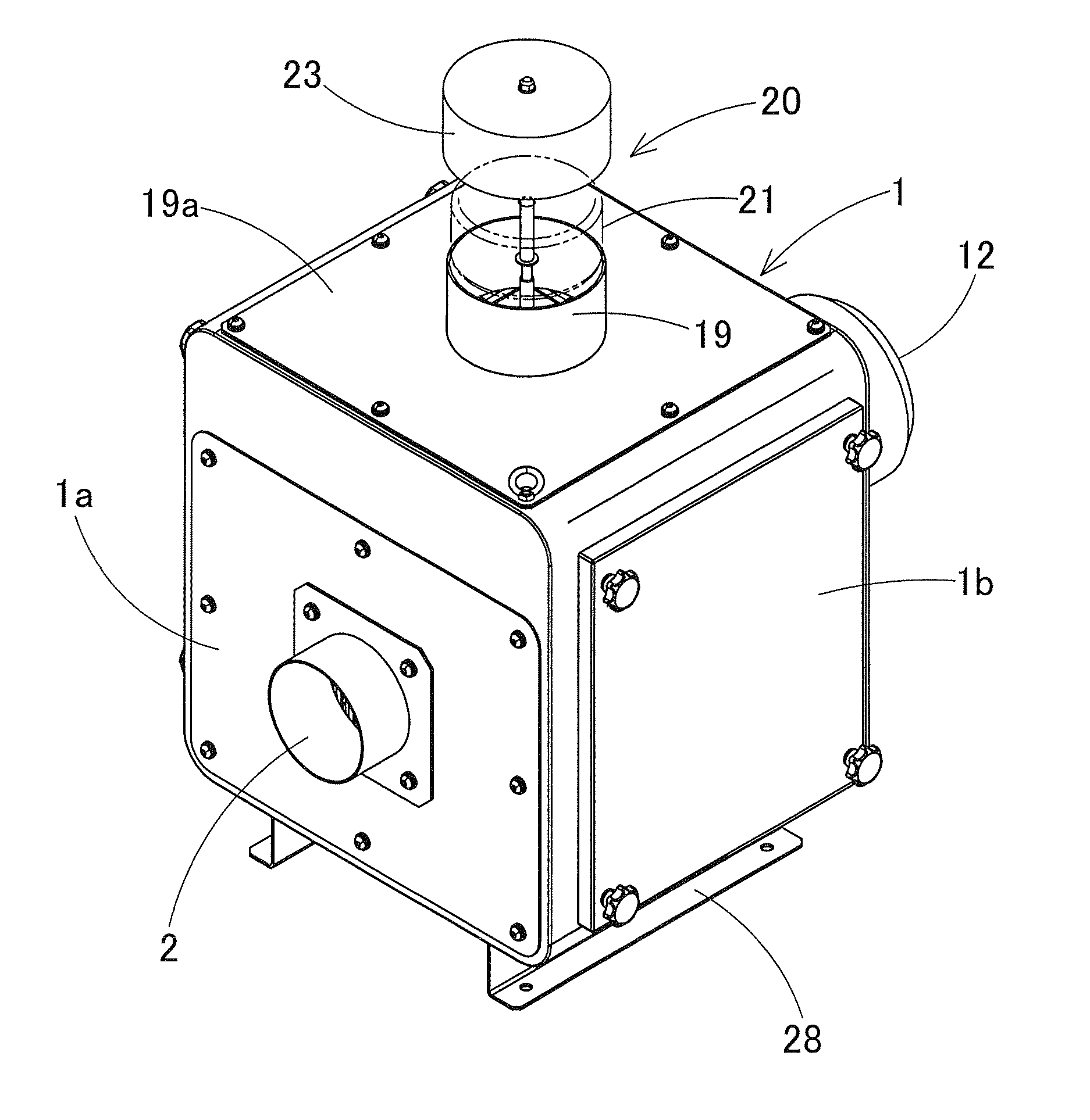
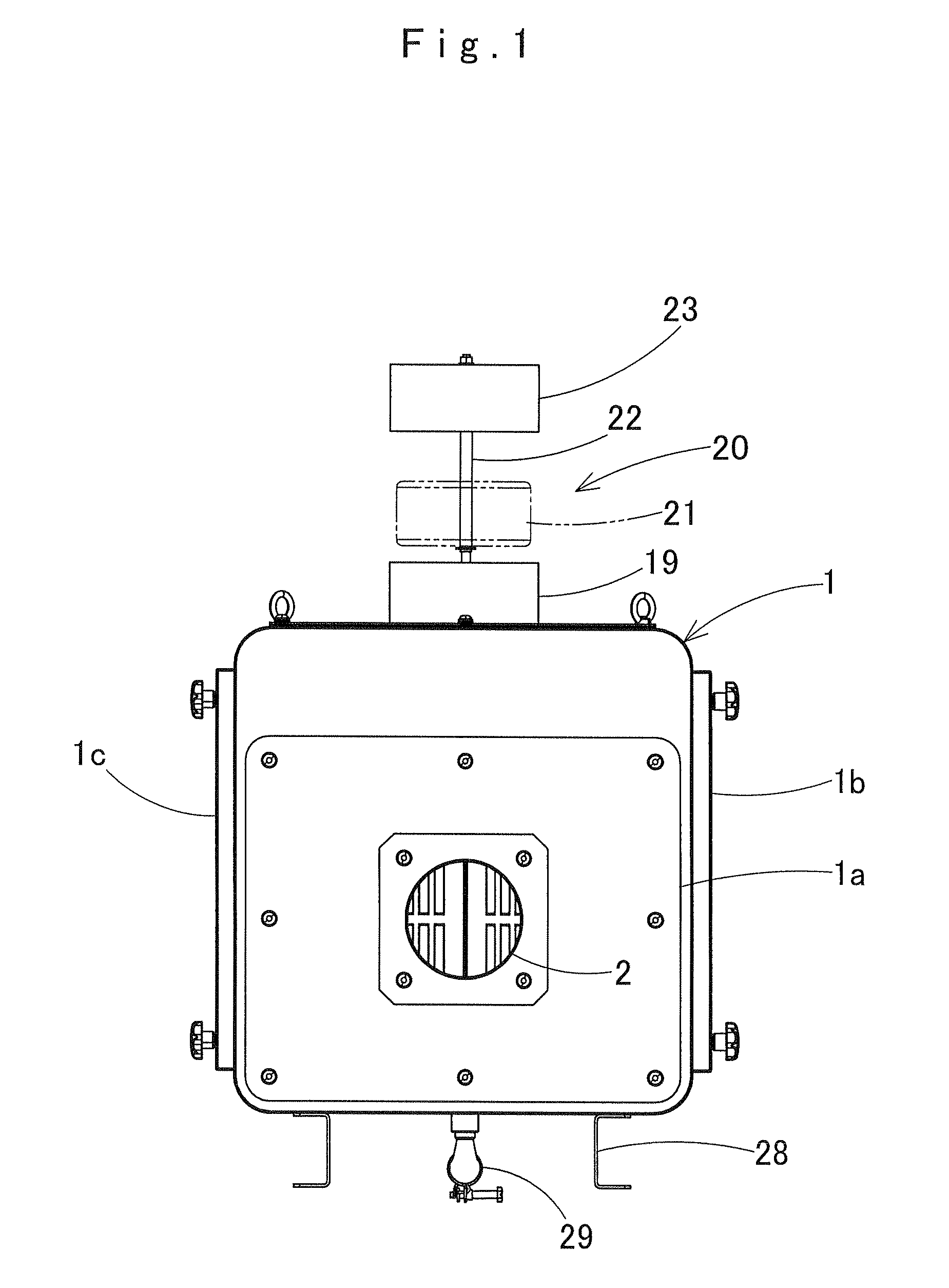
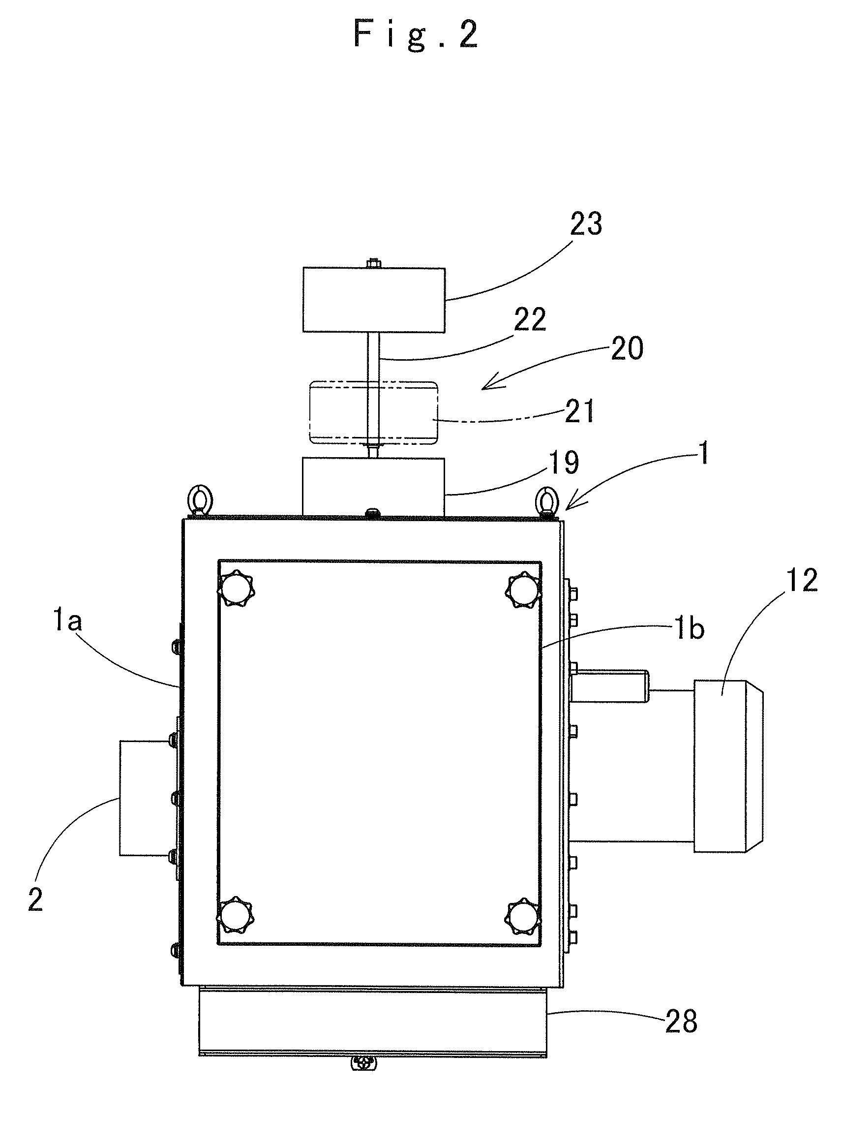
[0025]FIGS. 1 to 4 show a dust collector that collects dust laden fluid such as oil mist (including oil smoke), which contains fine dust generated in a machine tool in a machine shop.

[0026]Schematically, the dust collector is comprised of a generally rectangular parallelepiped casing 1 provided with a suction port 2 on the front. The casing 1 internally includes a main filter 5 as a dust collecting filter, a suction chamber 3 communicating with the suction port 2, an aspiration chamber 8 communicating with the suction chamber 3, an aspiration device 10 mounted on a back side of the casing 1 such that a fan 11 is located in the aspiration chamber 8, an exhaust ...


PUM

PropertyMeasurementUnit
pressureaaaaaaaaaa
temperatureaaaaaaaaaa
rotation angleaaaaaaaaaa

Abstract

A clog indicating device indicating clogging of a dust collecting filter in a dust collector is disclosed. The dust collector includes on an upper region of its casing an exhaust port opening upward, and a cover member is mounted interspatially above the exhaust port. A colored indicating float is so located as to be movable upward between the exhaust port and the cover member due to pressure of an air exhausted from the exhaust port. Clogging of a dust collecting filter is indicated according to a degree of exposure or a position in an up and down direction of the indicating float between the exhaust port and the cover member.

Description

CROSS REFERENCE TO RELATED APPLICATIONS[0001]The Present application claims priority from Japanese Patent Application No. 2011-209531 of Sakuragi et. al., filed on Sep. 26, 2011, the disclosure of which is hereby incorporated into the present application by reference.BACKGROUND OF THE INVENTION[0002]1. Field of the Invention[0003]The present invention relates to a clog detecting device that indicates clogging of a dust collecting filter in a dust collector for collecting dust laden fluid such as dust laden oil mist (including oil smoke) generated in a machine tool or the like in a shop.[0004]2. Description of Related Art[0005]In a shop doing machine work, machine tools generate dust laden oil mist or the like. If left untreated, the oil mist not only makes working environment of the shop worse by causing bad odor in the shop, intrusion of the dust laden fluid into equipment and its control panels and dirt of walls, but also makes the floor of the shop slippery, which may cause fall ...

Claims


Application Information

Patent Timeline
Patent Type & Authority Patents(United States)
IPC IPC(8): B01D46/42B01D46/00B01D46/46
CPCB01D46/42Y10S55/34B01D46/0086Y10S116/25
Inventor SAKURAGI, SATOSHIKAMAKURA, YOSHIFUMI
Owner AOI SEIKO
Why Eureka
Try Eureka