
Structural panel with ballistic protection

a technology of ballistic protection and structural panels, applied in protective equipment, transportation and packaging, weapons, etc., can solve the problems of reducing mission capabilities and adding weight, and achieve the effects of reducing the total weight of the armor-structure system, reducing deflection, and limiting crack propagation

Inactive Publication Date: 2014-10-28
SIKORSKY AIRCRAFT CORP
View PDF39 Cites 9 Cited by
  • Summary
  • Abstract
  • Description
  • Claims
  • Application Information

AI Technical Summary

Benefits of technology

The system effectively defeats Armor Piercing rounds with reduced weight, allowing for increased payload and range by integrating armor into the airframe structure, providing scalable protection against various projectile threats.

Problems solved by technology

Although effective, these parasitic solutions may result in added weight which may reduces mission capabilities.

Method used


Image

  • Structural panel with ballistic protection
  • Structural panel with ballistic protection
  • Structural panel with ballistic protection

Examples


Embodiment Construction

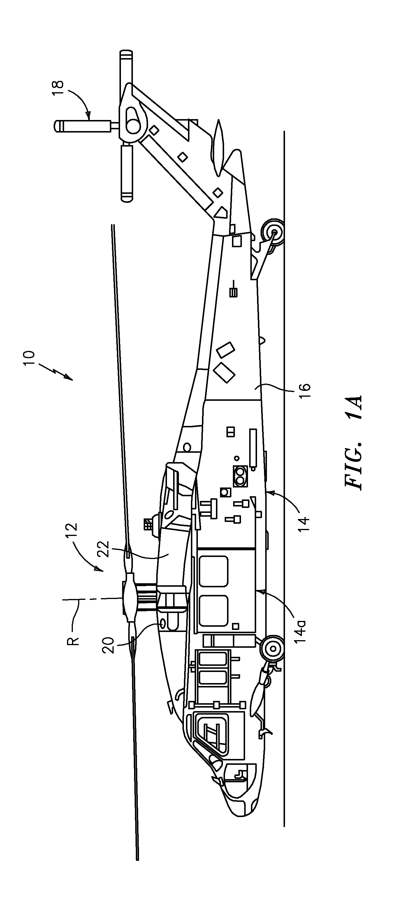
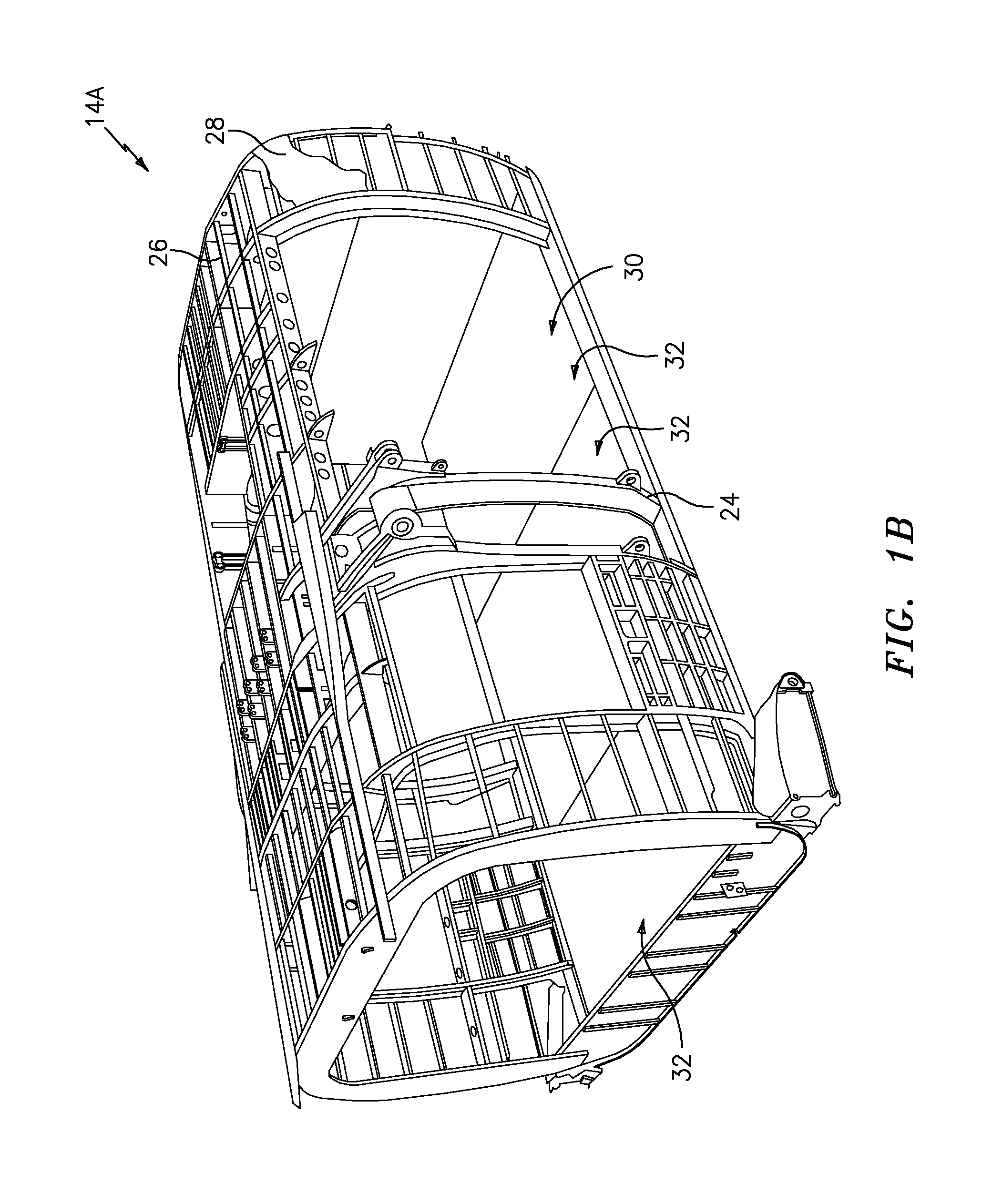
[0032]FIG. 1A schematically illustrates a rotary-wing aircraft 10 having a main rotor system 12. The aircraft 10 includes an airframe 14 having an extending tail 16 which mounts a tail rotor system 18, such as an anti-torque system. The airframe 14 includes an armored airframe section 14A. It should be understood that any airframe section may include armored panels as described below. The main rotor assembly 12 is driven about an axis of rotation R through a main gearbox (illustrated schematically at 20) by one or more engines 22. The main rotor system 12 includes a multiple of rotor blades mounted to a rotor hub. Although a particular helicopter configuration is illustrated and described in the disclosed embodiment, other configurations and / or machines, such as high speed compound rotary wing aircraft with supplemental translational thrust systems, dual contra-rotating, coaxial rotor system aircraft, turbo-props, tilt-rotors and tilt-wing aircraft, will also benefit from the presen...


PUM

PropertyMeasurementUnit
thickaaaaaaaaaa
thickaaaaaaaaaa
thickaaaaaaaaaa

Abstract

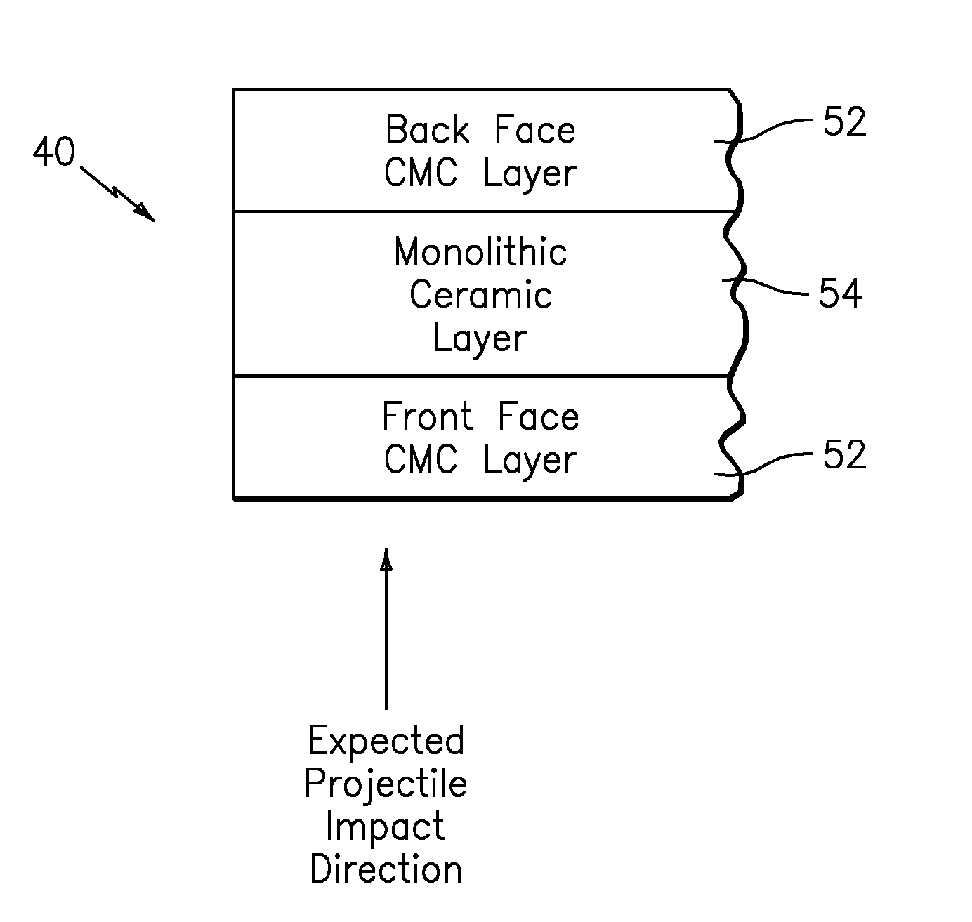
An armor system which integrates ballistic protection into load bearing structure. Each armored panel is manufactured as a sandwich structure having a multiple of layers including a hard ballistic material layer of a Ceramic / CMC hybrid armor material capable of defeating high velocity Armor Piercing projectiles.

Description

[0001]The present application is a Continuation-In-Part application of U.S. patent application Ser. No. 11 / 627,491, filed Jan. 26, 2007 now U.S. Pat. No. 8,709,584 (which claims the benefit of U.S. Provisional Patent Application No. 60 / 764,047, filed Jan. 31, 2006), and U.S. patent application Ser. No. 11 / 682,390, filed Mar. 6, 2007 (which claims the benefit of U.S. Provisional Patent Application No. 60 / 794,276, filed Apr. 20, 2006).BACKGROUND OF THE INVENTION[0002]The present invention relates to an armor system, and more particularly to a lightweight armor panel system which is integrated into an airframe as load bearing structure.[0003]Conventional armor systems for aircraft are often a type of appliqué armor in which parasitic armor, such as steel plates are placed over existing aircraft structure in critical areas so as to defeat small arms fire. Although effective, these parasitic solutions may result in added weight which may reduces mission capabilities.[0004]Accordingly, it...

Claims


Application Information

Patent Timeline
Patent Type & Authority Patents(United States)
IPC IPC(8): F41H5/04B64C27/04B64D9/00F41H5/013F41H5/00B64C1/20B64D7/00
CPCF41H5/0421Y02T50/46F41H5/013F41H5/0428B64C1/20B64C27/04B64D9/003B64D7/00Y02T50/40
Inventor TOWNSEND, WILLIAM A.CARSTENSEN, THOMAS A.BIRD, CONNIE E.HOLOWCZAK, JOHN E.
Owner SIKORSKY AIRCRAFT CORP
Learn More