Nozzle plate and atomizing module using the same

a technology of atomizing module and nozzle plate, which is applied in the field of atomizers to achieve the effects of suppressing low-frequency vibration, increasing atomizing area, and improving the stability of atomizing process

Active Publication Date: 2014-10-28
MICRO BASE TECH CORP
View PDF4 Cites 2 Cited by
  • Summary
  • Abstract
  • Description
  • Claims
  • Application Information

AI Technical Summary

Benefits of technology

[0018]Therefore, it is a primary objective of the present invention to provide a nozzle plate and an atomizing module using the nozzle plate, wherein the nozzle plate includes a plurality of protrusions formed thereon and a multi-curved surface structure radially or circularly arranged to achieve the effects of increasing an atomizing area, improving the stability of the atomization process, suppressing low-frequency vibrations and reducing the tensile stress for the manufacture.

Problems solved by technology

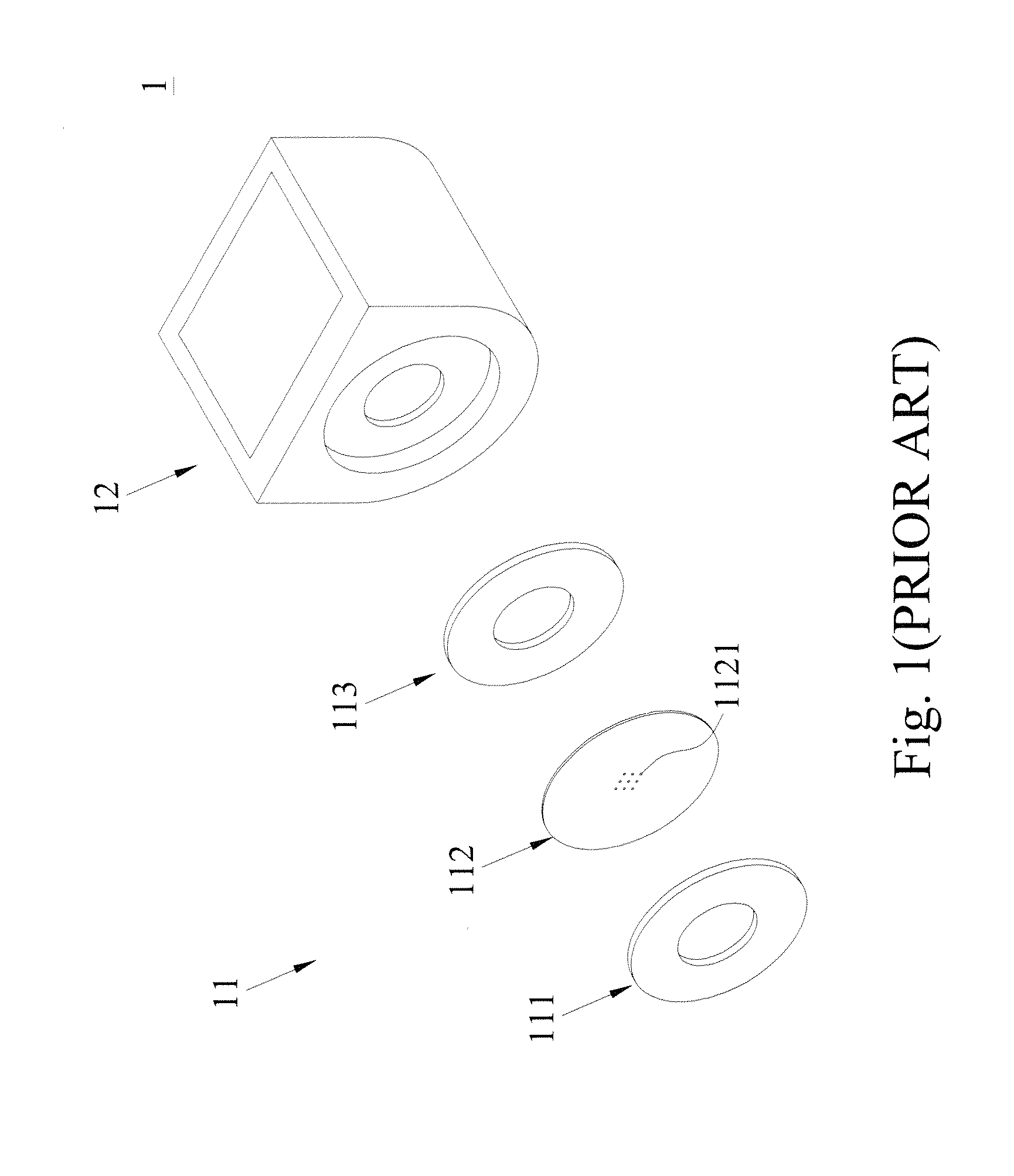
1. When the piezoelectric circular plate 113 vibrates, the produced vibration waves are transmitted in a direction from the external periphery of the nozzle plate 112 to the center of the nozzle plate 112, so that too much vibration energy is concentrated at the center of the nozzle plate 112, and the center area of the nozzle plate 112 has a too-large amplitude, and thus resulting in cracking or breaking the nozzle plate 112 easily by stress, and shortening the service life of the nozzle plate.
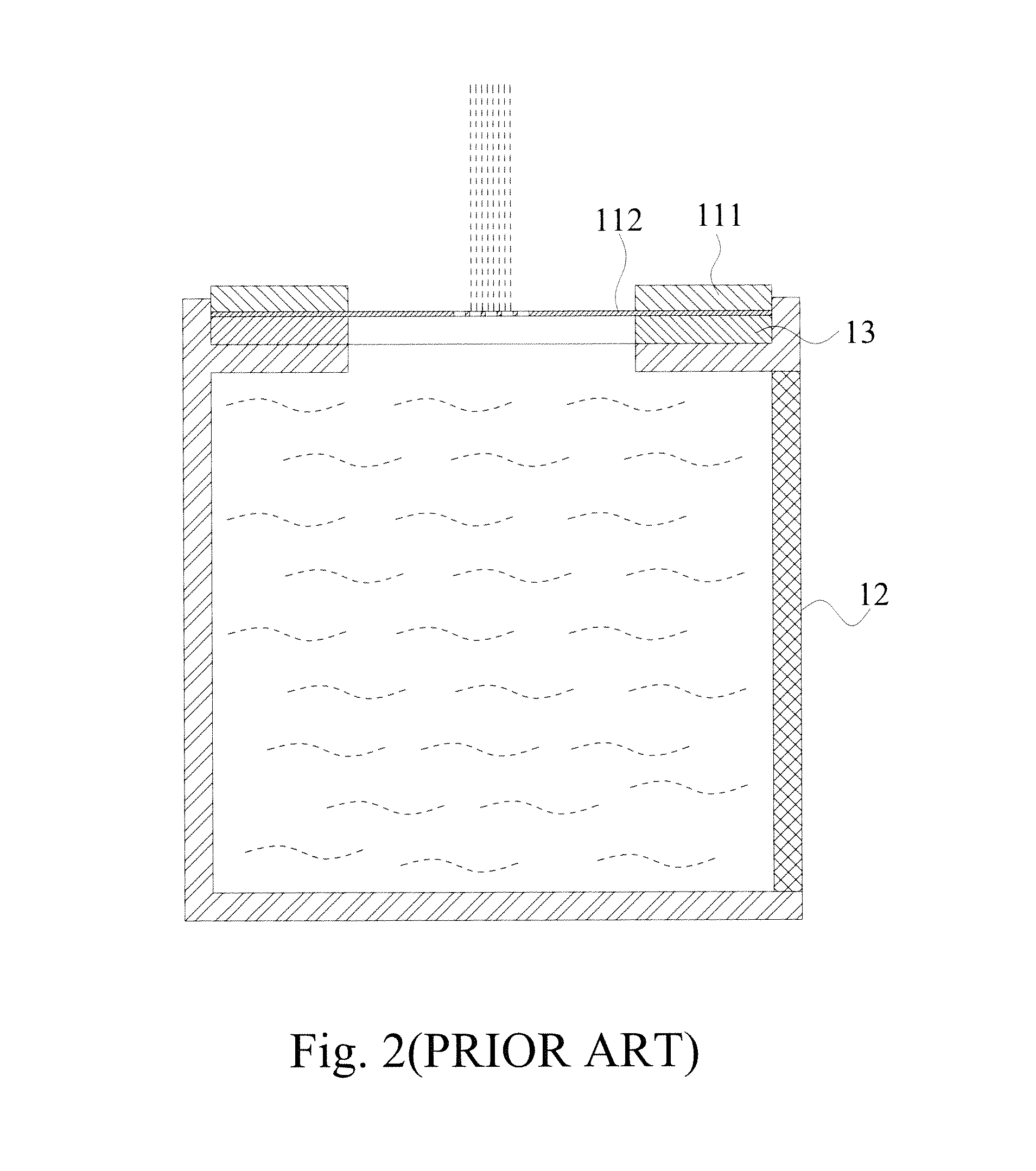
2. The vibration energy is concentrated at the center of the nozzle plate 112, so that an atomizing area is formed at the center of the nozzle plate 112 only. Since the atomizing area is situated at the center of the nozzle plate 112, an effective use of the firing holes 1121 of the nozzle plate 112 causes a poor atomization.
3. The atomization process requires a liquid-gas exchange to maintain a balance between internal and external pressures of an atomizing device. Due to the too-small atomizing area, the spray is unstable, and the flow of the sprayed liquid is unsteady.
4. The atomizing area is concentrated at the center area, and the molecular density of the atomized liquid is too large, so that liquid drops will collide easily to form liquid drops of a large diameter and lower the atomization efficiency.
1. When the nozzle plate 22 with the hemispherical surface structure is manufactured, the processing depth is inversely proportional to the curvature of the hemispherical surface due to the features of the manufacturing materials and properties. To achieve the effect of improving the atomization, the manufacturing depth at the center of the nozzle plate 22 must be equal to a certain depth. The smaller the curvature of the hemispherical surface, the easier is the manufacture for the required depth. To achieve the depth for the best atomization performance of the hemispherical surface, it is necessary to reduce the effective atomization range. In order to increase the effective atomization range, the radius of curvature for the manufacture must be increased. As a result, the manufacturing depth becomes shallow, and the atomization performance becomes lower. If it is necessary to achieve a smaller radius of curvature under the condition of the same size, a too-large stress will be exerted onto the nozzle plate 22 easily, and the structure will exceed the limit of deformation and end up with a crack or break, or the yield strength drops, so that the nozzle plate will be cracked or broken easily after the nozzle plate is vibrated for several times.
2. Due to the properties of the material of the nozzle plate 22, a greater diameter of the manufactured hemispherical surface will decrease the structural tension, weaken the inputted force and reduce the low-frequency resonance resisting capability, so that noises may be produced easily.
3. The packaged structure with this atomization method can clamp the nozzle plate 22 stably, and the internal diameter of the braking circular plate 21 is generally smaller than the internal diameter of the piezoelectric circular plate 23, and a vast majority of the vibration energies is transmitted to the nozzle plate 22, and the peripheral vibration area of the hemispherical surface design incapable of atomizing a liquid can be eliminated, and a portion of the firing holes 221 of the nozzle plate 22 has a lower utility rate, so that the atomizing area and the atomization on the nozzle plate 22 will be reduced. In addition, when the piezoelectric circular plate 21 is operated, adhesive is applied between layers of the piezoelectric circular plate 21, the nozzle plate 22 and the braking circular plate 23 and the force applying arms are of different lengths, the adhesion between components will be malfunctioned easily.
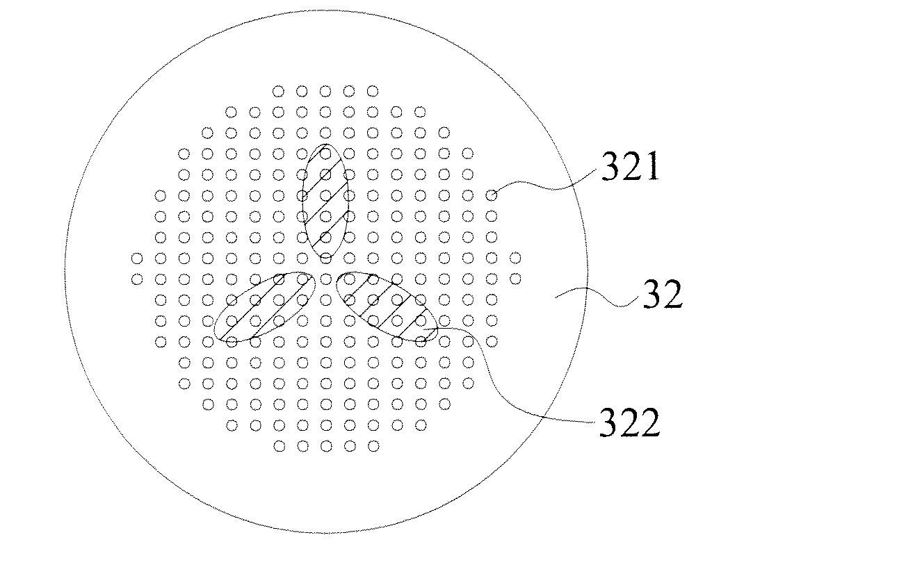
4. In the design of the hemispherical surface structure of the conventional nozzle plate, most of the transmitted energies of vibration waves are still concentrated at the center area, so that the micro holes formed at the center area have effective actions, but the vibration energy at the micro holes formed at the peripheral area is insufficient for an effective use, and the atomizing area cannot meet the design requirement.

Method used


Image

  • Nozzle plate and atomizing module using the same
  • Nozzle plate and atomizing module using the same
  • Nozzle plate and atomizing module using the same

Examples


Embodiment Construction

[0059]The technical content of the present invention will become apparent by the detailed description of the following embodiments and the illustration of related drawings as follows.

[0060]With reference to FIGS. 7a, 7b, 8 and 9 for an exploded view, a perspective view, a cross-sectional view and a schematic planar view of a nozzle plate and an atomizing module using the nozzle plate in accordance with the first preferred embodiment of the present invention respectively, the atomizing module 3 is installed on a side of a cavity 34 and comprises a piezoelectric circular plate 31, a nozzle plate 32 and a braking circular plate 33.

[0061]The piezoelectric circular plate 31 is made of a piezoelectric ceramic material including lead zirconate titanate, and has an external diameter 311 and an internal diameter 312.

[0062]The braking circular plate 33 is a metal circular plate having an external diameter 331 and an internal diameter 332, and installed on a side of the piezoelectric circular ...


PUM


Abstract

A nozzle plate and an atomizing module using the nozzle plate are disclosed. The atomizing module is installed at a cavity and includes a piezoelectric circular plate, a braking circular plate and a nozzle plate. The braking circular plate is installed on a side of the piezoelectric circular plate. The nozzle plate is a circular disc clamped between the piezoelectric circular plate and the braking circular plate, and the nozzle plate includes firing holes and first protrusions. Each first protrusion is non-circular and protruded in a direction towards the piezoelectric circular plate or the braking circular plate to form a multi-curved surface structure radially or circularly arranged into a specific geometric pattern. The nozzle plate can increase the atomizing area, atomizing quantity and liquid-gas exchange rate to prevent excessive stresses from concentrating at the center of the nozzle plate or vibrations from cracking or breaking the nozzle plate.

Description

CROSS-REFERENCE TO RELATED APPLICATIONS[0001]This non-provisional application claims priority under 35 U.S.C. §119(a) on Patent Application No(s). 100104897 filed in Taiwan, R.O.C. on Feb. 15, 2011, the entire contents of which are hereby incorporated by reference.BACKGROUND OF THE INVENTION[0002]1. Field of the Invention[0003]The present invention relates to an atomizer, in particular to a nozzle plate with a multi-curved surface structure having a geometric pattern radially or circularly arranged at the center of the nozzle plate, and an atomizing module using the nozzle plate.[0004]2. Description of the Related Art[0005]In general, an atomizer including an ultrasonic atomizer is made of a piezoelectric (PZT) ceramic material such as lead zirconate titanate. After a voltage is supplied, the ceramic material and a bundled metal back panel may be expanded, contracted or deformed, and energy is transmitted in form of waves, so that a vibration produced falls within a nanometer scale ...

Claims


Application Information

Patent Timeline
Patent Type & Authority Patents(United States)
IPC IPC(8): B05B1/14
CPCB05B17/0646
Inventor HSIEH, SHU-PINSU, YU-JUHUANG, CHIA-CHENLIN, CHIEN-HUAHSU, YU-CHUNGLIN, TAI-SHUANHUANG, MEI-HUIHSIUNG, CHIEH-MING
Owner MICRO BASE TECH CORP
Why Eureka
Try Eureka