Power control unit

a power control unit and power control technology, applied in the field of power control units, can solve problems such as the decrease of the running performance of the vehicle, and achieve the effect of ensuring the cooling ability of the power control uni

Active Publication Date: 2014-11-04
TOYOTA JIDOSHA KK +1
View PDF29 Cites 19 Cited by
  • Summary
  • Abstract
  • Description
  • Claims
  • Application Information

AI Technical Summary

Benefits of technology

[0013]One aspect of the invention relates to a power control unit that controls a rotary electric machine that drives a vehicle, and that is mounted onto a motor case in which the rotary electric machine is housed. This power control unit includes a fixed base that is made of resin; a cooler that is arranged on the fixed base and that includes a power module; and a control substrate that is arranged on the cooler. The fixed base inhibits conduction of heat from the motor case to the power control unit. This kind of structure enables the conduction of heat from the motor case to be inhibited, so a decrease in output that accompanies a rise in temperature of the power module can be prevented.
[0016]In the power control unit having the structure described above, thin plate made of metal that inhibits the conduction of heat between the cooler and the fixed base, and fixing means for fixing the cooler, the thin plate, and the fixed base together, may be provided with the fixed base. The thin plate may form a space that is surrounded by the cooler and the thin plate, and the thin plate may be cooled by the cooler. According to this kind of structure, the space between the cooler and the thin plate can be used effectively, and the space between the fixed base and the thin plate can also be used as an insulating chamber, so convection heating from heated air can be prevented.
[0017]In the power control unit having the structure described above, an electronic device may be arranged in the space that is surrounded by the cooler and the thin plate. This kind of structure makes it possible to effectively cool the electronic device with the cooler.
[0021]The invention makes it possible to provide a power control unit that is mounted in such as way that the temperature of the power control unit is able to be prevented from rising, and thus the cooling ability of the power control unit is able to be ensured, even when the step up converter and the inverter that form the power control unit are housed together with the motor in a single case, by inhibiting heat conduction from the case, heat conduction from the cover that covers the power control unit, and convection heat of the air inside the cover.

Problems solved by technology

Normally temperature regulation is performed by a large radiator and fan, but if heat exceeding the capacity of the cooler 108 is transferred to the cooler 108 in a heavy load state, the running performance of the vehicle may decrease due to output limiting control that accompanies a rise in the temperature of the power elements.

Method used


Image

  • Power control unit
  • Power control unit
  • Power control unit

Examples


Embodiment Construction

[0028]Hereinafter, example embodiments of the invention will be described with reference to the accompanying drawings.

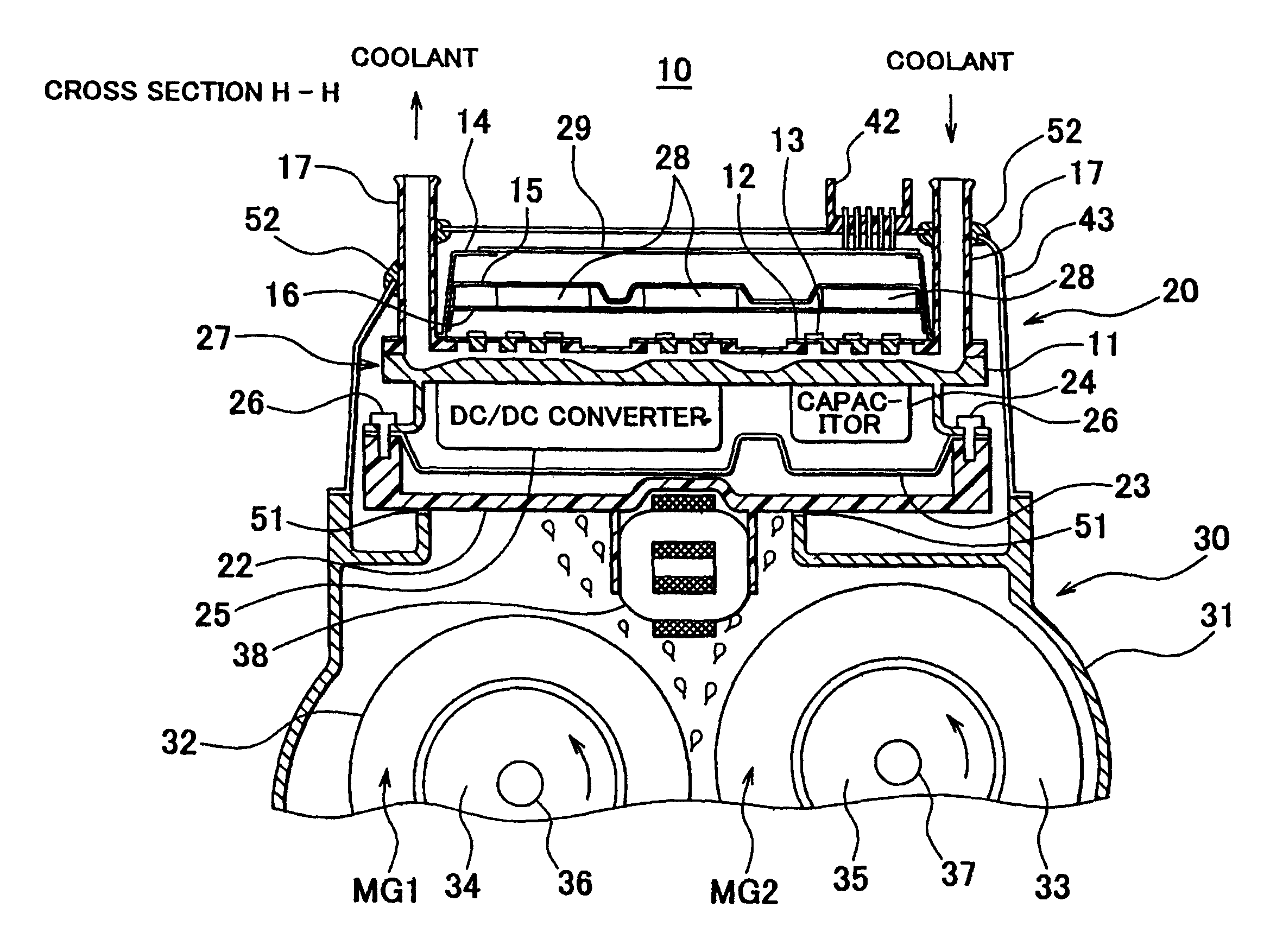
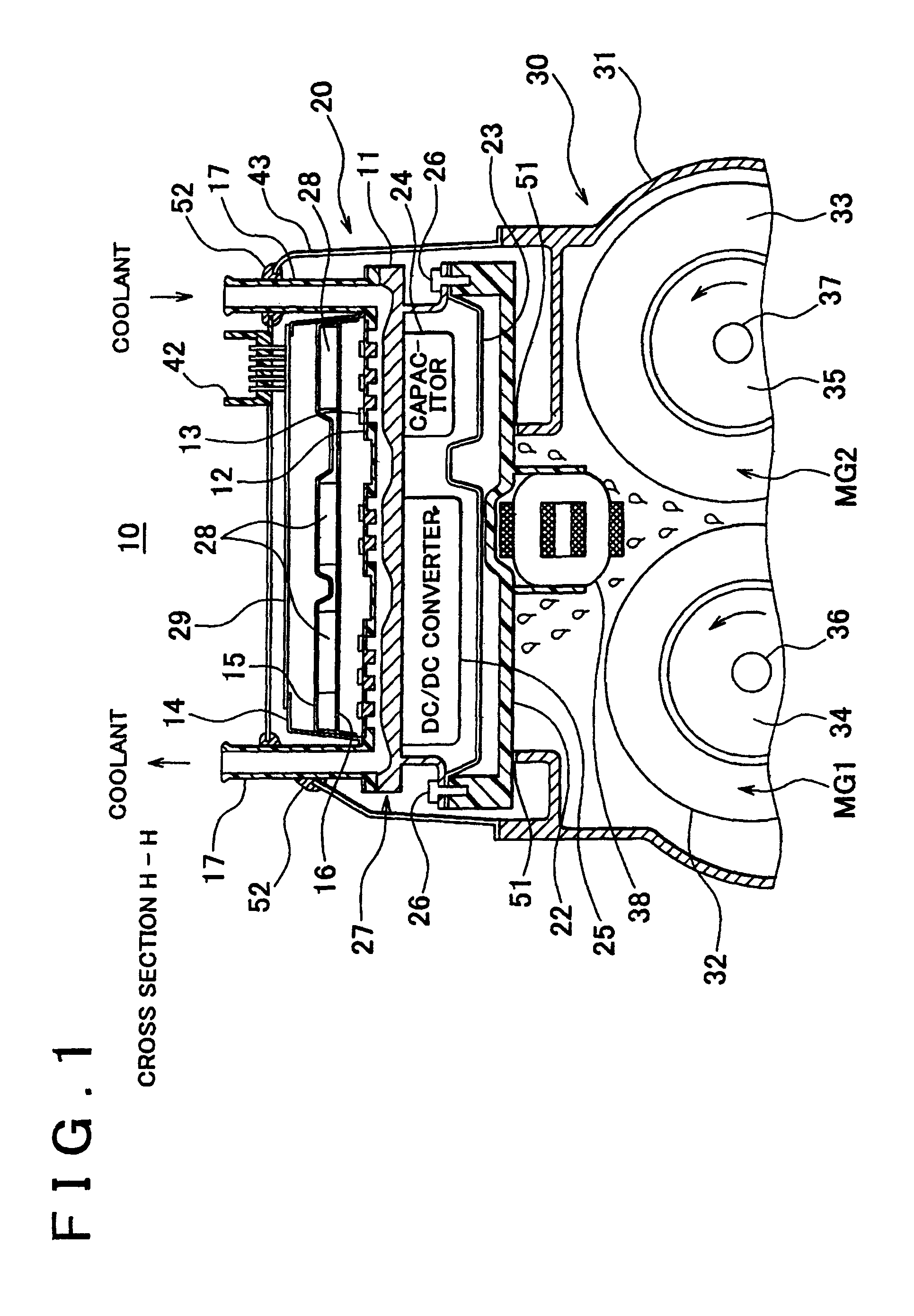
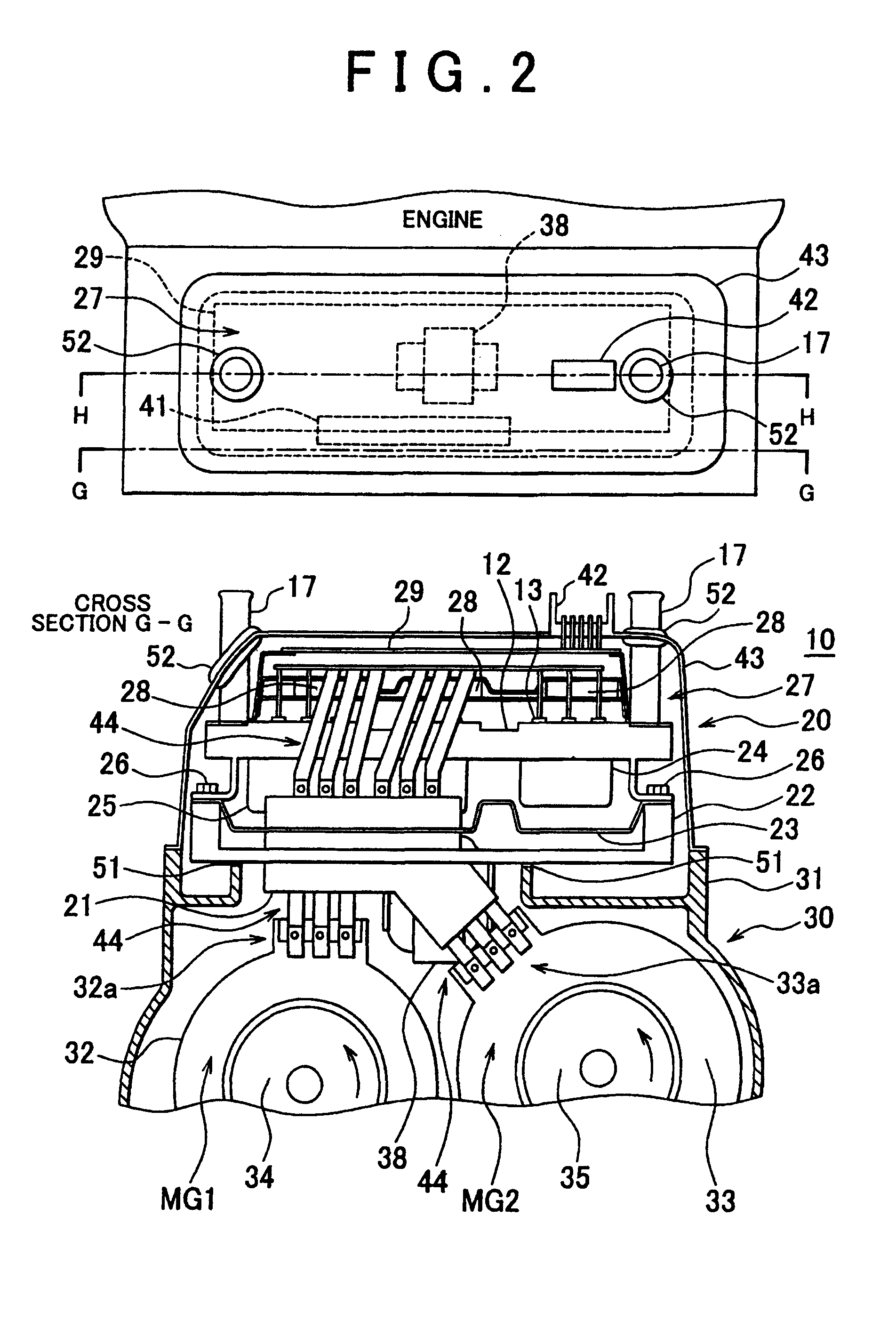
[0029]FIG. 1 is a view of a drive apparatus 10 with a power control unit (PCU), and FIG. 2 is a front view and a plan view of the drive apparatus 10 shown in FIG. 1. The upper portion of FIG. 2 is a plan view of the drive apparatus 10, and the lower portion of FIG. 2 is a front view of a cross section taken along line G-G. First, the overall structure of the drive apparatus 10 will be briefly described with reference to FIG. 2.

[0030]The drive apparatus 10 in FIG. 2 includes a transaxle 30 that has motor-generators MG1 and MG2 that are connected to an engine via a power distributing apparatus, a fixed base 22 that is made of resin and is arranged covering an open portion of a transaxle case 31, a thin plate 23 made of steel sheet that is arranged on the fixed base 22, a cooler 27 arranged on the thin plate 23, smoothing capacitors 28 arranged above the cooler 27, a co...


PUM


Abstract

A power control unit that controls a rotary electric machine that drives a vehicle, and that is mounted onto a motor case in which the rotary electric machine is housed, includes a fixed base that is made of resin; a cooler that is arranged on the fixed base and that includes a power module; and a control substrate that is arranged on the cooler. The fixed base inhibits conduction of heat from the motor case to the power control unit.

Description

CROSS REFERENCE TO RELATED APPLICATION[0001]This is a national phase application based on the PCT International Patent Application No. PCT / IB2012 / 000223 filed on Feb. 8, 2012, claiming priority to Japanese application No. 2011-027054, filed Feb. 10, 2011, the entire contents of both of which are incorporated herein by reference.BACKGROUND OF THE INVENTION[0002]1. Field of the Invention[0003]The invention relates to a power control unit that controls a rotary electric machine that drives a vehicle, and that is mounted onto a motor case in which the rotary electric machine is housed.[0004]2. Description of Related Art[0005]Electric vehicles in which the vehicle is driven by driving force from a rotary electric machine such as a motor-generator, hybrid vehicles in which the vehicle is driven by a combination of a rotary electric machine and an engine that is an internal combustion engine, and fuel cell vehicles in which the vehicle is driven by electric power generated by a fuel cell, ...

Claims


Application Information

Patent Timeline
Patent Type & Authority Patents(United States)
IPC IPC(8): H02K9/19B60R13/08B60K11/02B60K1/00B60K6/405
CPCH02K9/19B60K2001/003B60Y2306/05B60K6/405B60Y2400/61B60R13/0876B60K11/02
Inventor ASAKURA, KENHOTTA, YUTAKAUECHI, TATSUYUKI
Owner TOYOTA JIDOSHA KK
Why Eureka
Try Eureka