High performance, highly energy efficient precast composite insulated concrete panels

a composite, high-efficiency technology, applied in the direction of water-setting substance layered products, transportation and packaging, synthetic resin layered products, etc., can solve the problems of no insulation in places, little progress in designing truly energy-efficient exterior wall systems, and the majority of energy loss. achieve the effect of thinness and strength

Active Publication Date: 2014-11-04
CIUPERCA ROMEO ILARIAN
View PDF153 Cites 56 Cited by
  • Summary
  • Abstract
  • Description
  • Claims
  • Application Information

AI Technical Summary

Benefits of technology

[0014]In order to build the highest energy efficient building, energy loss through the building envelope must be reduced or eliminated. To eliminate or reduce the most energy loss, the exterior wall should be constructed of materials with the highest thermal mass facing the inside climate controlled (i.e., heated or cooled) space of the building, completely insulated from the environment with the most amount of heat conduction insulating material, such as closed cell foam insulation and / or refractory insulating material, and an exterior wall cladding system with the least amount of thermal mass. It is also desirable to have integrated in such a panel, a wide variety of architectural finishes. The present invention satisfies the foregoing needs by providing an improved precast concrete panel system.

Problems solved by technology

In buildings, the majority of energy loss takes place through the building envelope and the HVAC air intake / exhaust system.
While great progress has been made improving the energy efficiency of roof, door and window systems, very little progress has been made in designing truly energy-efficient exterior wall systems.
However, there are several drawback of this system.
Batt insulation may not completely fill the cavity wall and over time it can sag, leaving no insulation in places.
Moisture condensation inside the cavity wall is common which dampens and compresses the batt insulation.
When this occurs, the damp batt insulation loses most, if not all, insulating properties.
These pressure differences cause air to move through the exterior wall system.
Simply stated, cavity wall framed systems have poor energy efficiency, among many other problems.
Concrete has high thermal mass, which makes it rather expensive to heat or cool in extreme temperatures.
However, such insulation does little to improve energy efficiency as it is generally on the wrong side of the wall; i.e., the interior wall surface.
Concrete walls have the advantage that they are barrier systems; i.e., no air can flow through from inside to the outside, but still have poor energy efficiency.
However, this does little to improve energy efficiency since concrete thermal bridging surrounds each foam cell.
Brick walls have better insulating properties than concrete or CMU block walls, but still have poor energy efficiency.
Animals, such as woodpeckers, can cause severe damage to EIFS.
Furthermore, when applied over framing systems there is still a wall cavity to contend with, and drainage cavities are required to mitigate some of the issues associated with the use of EIFS, such as water intrusion, mold and others.
Moreover, application of EIFS requires scaffolding the entire building perimeter, which adds cost and time to a construction schedule.
Prior art precast concrete wall panels also have a large thermal mass when exposed to ambient temperatures.
Therefore, buildings built with precast concrete panels generally have relatively poor energy efficiency.
Such buildings usually require a relatively large amount of energy to keep them warm in the winter and cool in the summer.
This method however does not create a highly energy efficient building envelope.
And, since batt insulation of significant thickness is required the interior frame system takes valuable floor space and creates a cavity wall.
The second layer is therefore still relatively thick and heavy.
The weight of the second layer added to the weight of the first layer makes the entire panel relatively heavy.
Generally this is a costly system.
However these panels are heavier and therefore more expensive to manufacture.
The thinner the concrete wythes, the more brittle they become which requires use of pre-stressed cable reinforcement or expensive carbon fiber reinforcements.

Method used


Image

  • High performance, highly energy efficient precast composite insulated concrete panels
  • High performance, highly energy efficient precast composite insulated concrete panels
  • High performance, highly energy efficient precast composite insulated concrete panels

Examples


Embodiment Construction

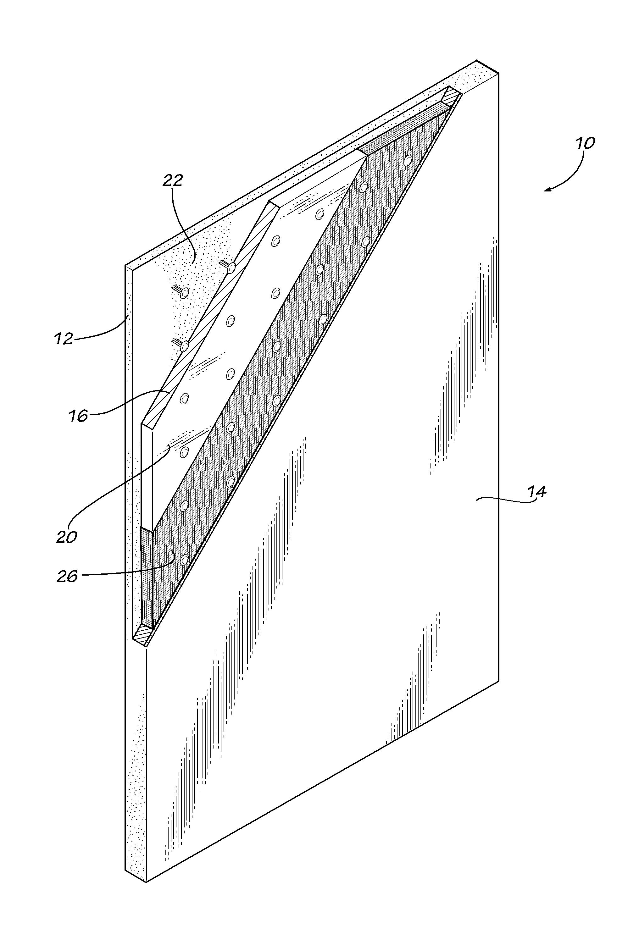
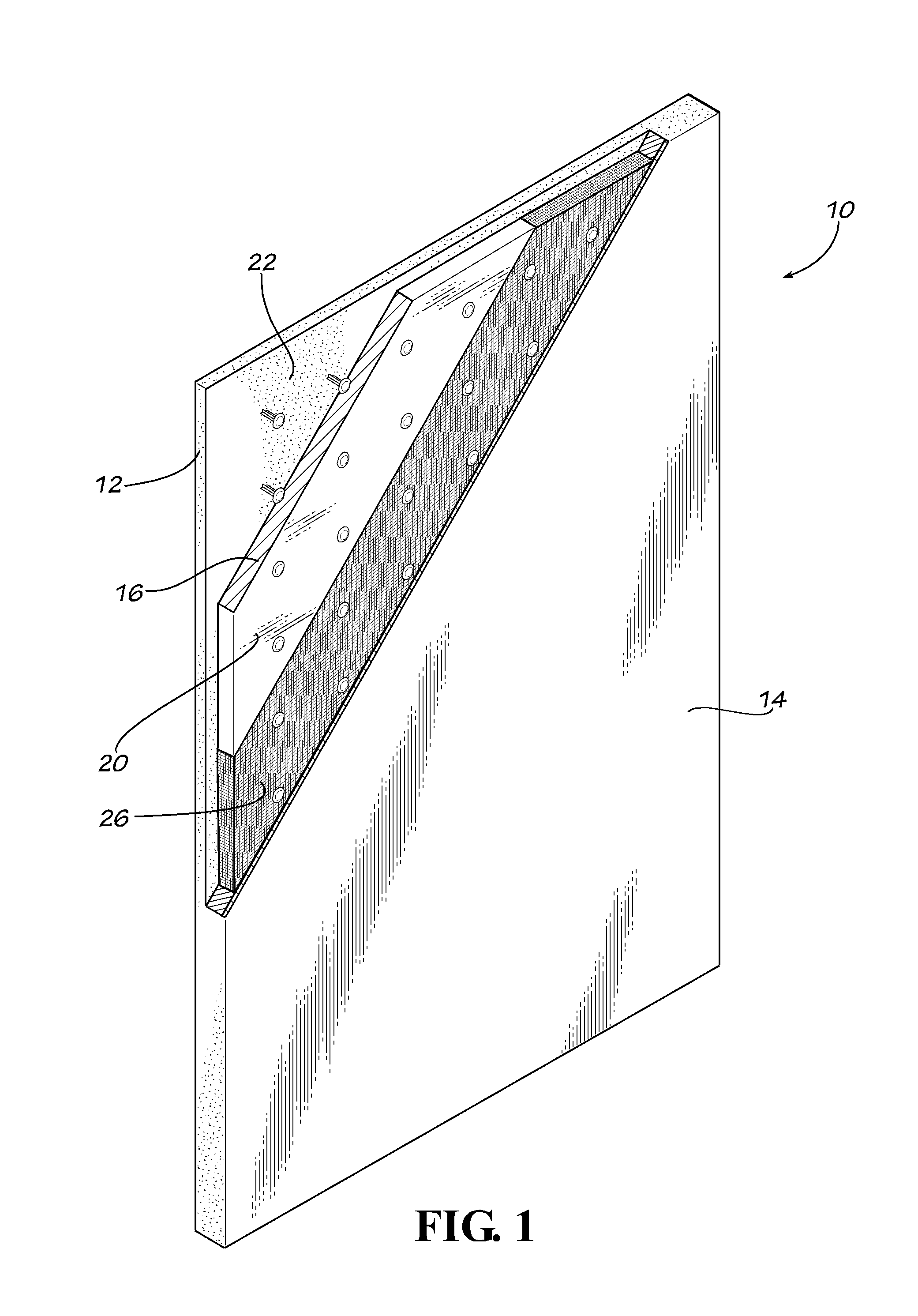
[0079]Referring now to the drawing in which like numbers indicate like elements throughout the several views, there is shown in FIG. 1 a disclosed embodiment of a lightweight composite insulated concrete panel 10 in accordance with the present invention. The panel 10 comprises an interior structural layer of concrete or structural interior wythe 12 and an exterior non-structural, architectural layer of concrete or non-structural exterior wythe 14. Disposed between the interior wythe 12 and the exterior wythe 14 is a foam insulating panel 16. The foam insulating panel has an interior primary surface 18 and an exterior primary surface 20. The exterior primary surface 20 defines a single continuous plane across the entire face of the foam insulating panel 16. The foam insulating panel 16 can be made from any insulating material that provides sufficient insulating properties. However, the foam insulating panel 16 preferably is made from a closed cell polymeric foam material, such as mol...


PUM

PropertyMeasurementUnit
thicknessaaaaaaaaaa
thickaaaaaaaaaa
weight ratioaaaaaaaaaa

Abstract

The invention comprises a relatively lightweight cementitious-based material panel. The cementitious-based material panel comprises a foam insulating panel having a first surface and a second surface; a first structural layer of cementitious-based material formed on the first surface of the foam insulating panel and affixed thereto; and a second non-structural layer of cementitious-based material formed on the second surface of the foam insulating panel and affixed thereto. The second non-structural layer of cementitious-based material is substantially thinner than the first structural layer of concrete. The second non-structural layer of cementitious-based material is preferably formed from polymer modified concrete, plaster or mortar. A method of making the cementitious-based material panel is also disclosed.

Description

FIELD OF THE INVENTION[0001]The present invention generally relates to the forming of concrete structures. More particularly, this invention relates to precast concrete structures, especially precast concrete panels. The present invention also relates to composite insulated precast concrete panels. The present invention further relates to methods of making composite insulated precast concrete structures, especially architectural precast concrete panels. The present invention also relates to high strength lightweight composite insulated precast concrete panels and to methods of making the same. The present invention relates to highly energy efficient building envelope and methods of achieving same.BACKGROUND OF THE INVENTION[0002]In the United States, approximately 40% of energy consumption is used to heat and cool buildings. In buildings, the majority of energy loss takes place through the building envelope and the HVAC air intake / exhaust system. The building envelope consists of do...

Claims


Application Information

Patent Timeline
Patent Type & Authority Patents(United States)
IPC IPC(8): B32B37/18B32B7/02E04C2/04B32B7/027B32B7/08
CPCB32B13/12E04C2002/047E04C2/044B32B7/02B32B7/08E04C2/2885E04F13/02B32B3/266B32B5/028B32B13/02B32B13/14B32B15/046B32B15/14B32B2307/304B32B2307/54B32B2307/718E04B5/02E04F2203/00Y10T428/2495Y10T428/24967Y10T428/249923B32B7/027
Inventor CIUPERCA, ROMEO, ILARIAN
Owner CIUPERCA ROMEO ILARIAN
Why Eureka
Try Eureka