
Semiconductor sensing device to minimize thermal noise

a sensing device and semiconductor technology, applied in the field of microelectromechanical system (mems) pressure sensing elements, can solve the problems of resistor stress, inaccurate pressure reading of the pressure sensing element, and affecting the pressure reading detected, so as to reduce or eliminate thermally induced stresses or thermal noise

Active Publication Date: 2014-11-11
VITESCO TECH USA LLC
View PDF7 Cites 15 Cited by
  • Summary
  • Abstract
  • Description
  • Claims
  • Application Information

AI Technical Summary

Benefits of technology

[0019]In some embodiments, a pressure sensor is designed to reduce or eliminate thermally induced stresses or thermal noise, such as temperature offset voltage output. The pressure sensor includes a pressure sensing element having a diaphragm, and a cavity formed as part of the pressure sensing element, where the cavity receives a fluid such that the diaphragm at least partially deflects. The pressure sensor also includes a plurality of piezoresistors connected to the pressure sensing element, which are operable to generate a signal based on the amount of deflection in the diaphragm. A top surface is formed as part of the pressure sensing element, and the plurality of piezoresistors are doped to the top surface. A plurality of outer surfaces is also formed as part of the pressure sensing element, such that each of the plurality of outer surfaces terminates into the top surface. At least one substrate is operable for supporting the pressure sensing element.
[0020]At least one trench is integrally formed as part of the pressure sensing element, and an adhesive connects the pressure sensing element to the at least one substrate such that at least a portion of the adhesive is disposed in the trench and redistributes thermally induced stresses on the piezoresistors such that the thermally induced stresses are substantially eliminated.

Problems solved by technology

The adhesive expands and contracts at a different rate in relation to the pressure sensing element, which can cause stress to be applied to the resistors, affecting the pressure reading detected by the pressure sensing element.
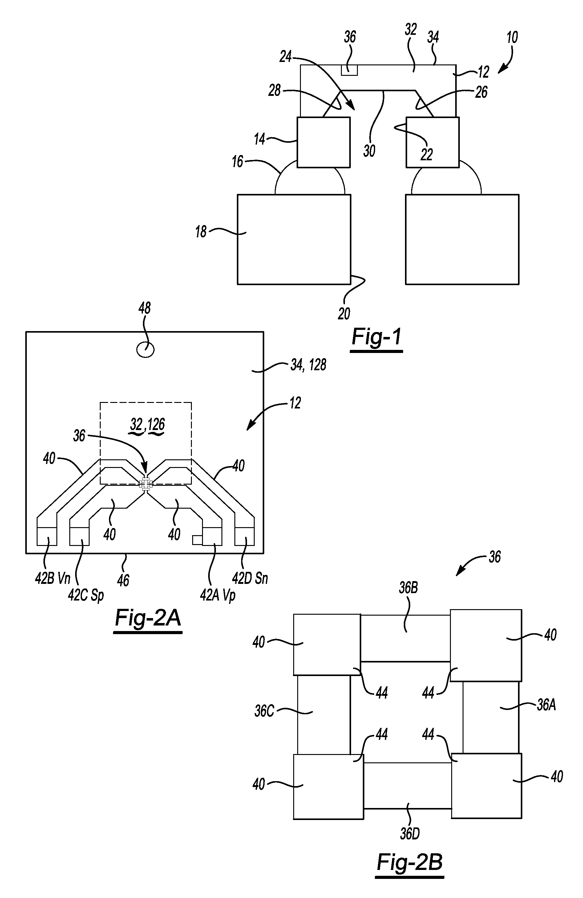
However, the difference in thermal expansion between the adhesive 16 and the pressure sensing element 12 has resulted in unwanted stresses being applied to the pressure sensing element 12, which then disrupt each of the resistors 36A-36D, causing an inaccurate pressure reading by the pressure sensing element 12.
The high TCO is difficult for an ASIC to compensate, especially when the adhesive 16 is not symmetrically dispensed.
If the adhesive is not symmetrically dispensed, this can further reduce the accuracy of the sensor.

Method used


Image

  • Semiconductor sensing device to minimize thermal noise
  • Semiconductor sensing device to minimize thermal noise
  • Semiconductor sensing device to minimize thermal noise

Examples


Embodiment Construction

[0035]The following description of the preferred embodiment(s) is merely exemplary in nature and is in no way intended to limit the invention, its application, or uses.

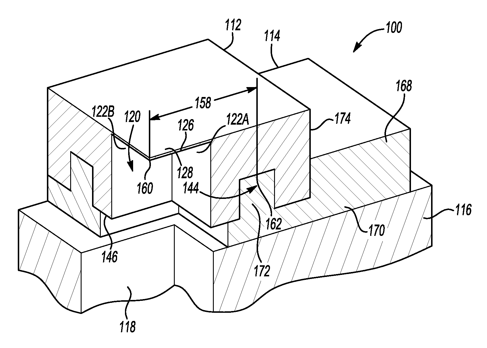
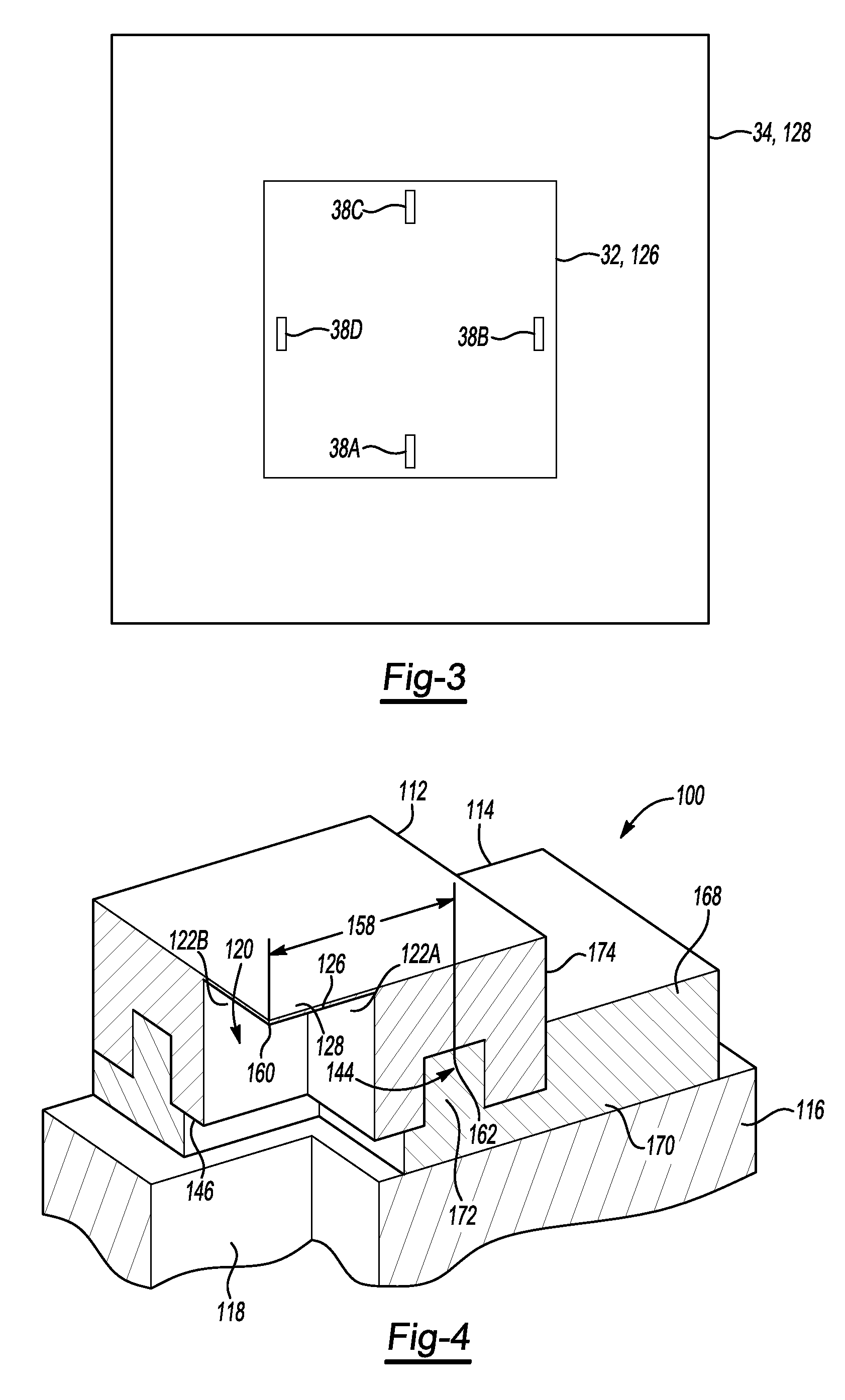
[0036]A pressure sensor according to embodiments of the present invention is shown in FIGS. 4-11, generally at 100. The sensor 100 includes a pressure sensing element 112, an adhesive 114, and a housing substrate 116. The pressure sensing element 112 shown in FIGS. 4-7 is made from silicon, and is connected to the housing substrate 116 using the adhesive 114.

[0037]Formed as part of the housing substrate 116 is an aperture 118. The aperture 118 is in fluid communication with a cavity, shown generally at 120, where the cavity 120 is formed as part of the pressure sensing element 112. In one embodiment, the cavity 120 is formed using a dry etch, deep reactive ion etch (DRIE), but it is within the scope of the invention that other processes may be used. The pressure sensing element 112 includes a plurality of substantiall...


PUM

PropertyMeasurementUnit
thicknessaaaaaaaaaa
thicknessaaaaaaaaaa
operating temperatureaaaaaaaaaa

Abstract

An MEMS pressure sensor is designed to reduce or eliminate thermal noise, such as temperature offset voltage output. The pressure sensor includes a pressure sensing element having a diaphragm, and a cavity formed as part of the pressure sensing element, where the cavity receives a fluid such that the diaphragm at least partially deflects. The pressure sensing element also includes a plurality of piezoresistors, which are operable to generate a signal based on the amount of deflection in the diaphragm. At least one trench is integrally formed as part of the pressure sensing element, and an adhesive connects the pressure sensing element to the at least one substrate such that at least a portion of the adhesive is attached to the trench and redistributes thermally induced stresses on the pressure sensing element such that the thermally induced noise is substantially eliminated.

Description

FIELD OF THE INVENTION[0001]Embodiments of the invention relate to a microelectromechanical system (MEMS) pressure sensing element having a trench at the backside for reducing or eliminating the effect of thermally induced stresses or thermal noise, such as temperature offset voltage output.BACKGROUND OF THE INVENTION[0002]MEMS pressure sensors are generally known. One type of pressure sensor is a differential pressure sensor which includes a pressure sensing element made of silicon which is anodically bonded to a glass pedestal, and the glass pedestal is mounted to a housing substrate using an adhesive. Many differential pressure sensors are used in applications in which the sensors are exposed to varying temperatures. This causes the sensing element, the glass pedestal, the adhesive, and the housing substrate to expand and contract in response to the temperature changes.[0003]The pressure sensing element includes four piezoresistors or resistors positioned in what is known as a “W...

Claims


Application Information

Patent Timeline
Patent Type & Authority Patents(United States)
IPC IPC(8): G01L7/08G01L9/06
CPCG01L19/04B81B7/0019G01L9/0054G01L9/0042B81C2203/032B81B2201/0264
Inventor CHIOU, JEN-HUANG ALBERTCHEN, SHIUH-HUI STEVEN
Owner VITESCO TECH USA LLC
Learn More