Rotor or stator for an electrodynamic machine with segment blocks constituting a stator or rotor ring and method for manufacturing such a stator or rotor

a technology of stator or rotor ring and electrodynamic machine, which is applied in the direction of dynamo-electric machines, electrical apparatus, magnetic circuits, etc., can solve the problems of reducing the design affecting placing limits on minimizing the stator size. , to achieve the effect of optimizing the power output or the size of the electrodynamic motor, reducing the size of the stator, and reducing the torqu

Inactive Publication Date: 2014-11-11
HANS MEIER
View PDF24 Cites 5 Cited by
  • Summary
  • Abstract
  • Description
  • Claims
  • Application Information

AI Technical Summary

Benefits of technology

[0010]Plate segment blocks offer the considerable advantage that they may be fitted with coil arrays before being combined into an annulus. Accordingly post-winding or mounting the coil arrays is no longer required, hence the otherwise needed space no longer is mandatory. As a result a much higher packing factor may be attained and easily may be well above 70%. As a result an electrodynamic motor may be designed which offers a larger torque for the same size. Therefore the power output or the size of the electrodynamic motor may be optimized; clearly a combination of improved power output and improved size also is feasible.
[0011]The plate segments prefera

Problems solved by technology

This manufacturing procedure incurs the substantial drawback that given a torque to be generated by the final electrodynamic motor, limits are placed on minimizing the stator size.
This drawback is also incurred regarding increasing the torque when the stator size is kept constant.
This difficulty arises in part because enough space must be allowed in the stator's inside space defined by the assembled plate segments for winding the coil arrays.
This procedure however negatively affects the stator design size because the subsequent stator insertion shall require more space for winding.
Another problem arisin

Method used


Image

  • Rotor or stator for an electrodynamic machine with segment blocks constituting a stator or rotor ring and method for manufacturing such a stator or rotor
  • Rotor or stator for an electrodynamic machine with segment blocks constituting a stator or rotor ring and method for manufacturing such a stator or rotor
  • Rotor or stator for an electrodynamic machine with segment blocks constituting a stator or rotor ring and method for manufacturing such a stator or rotor

Examples


first embodiment

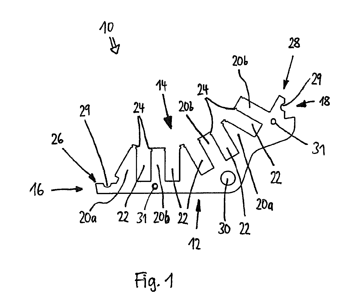
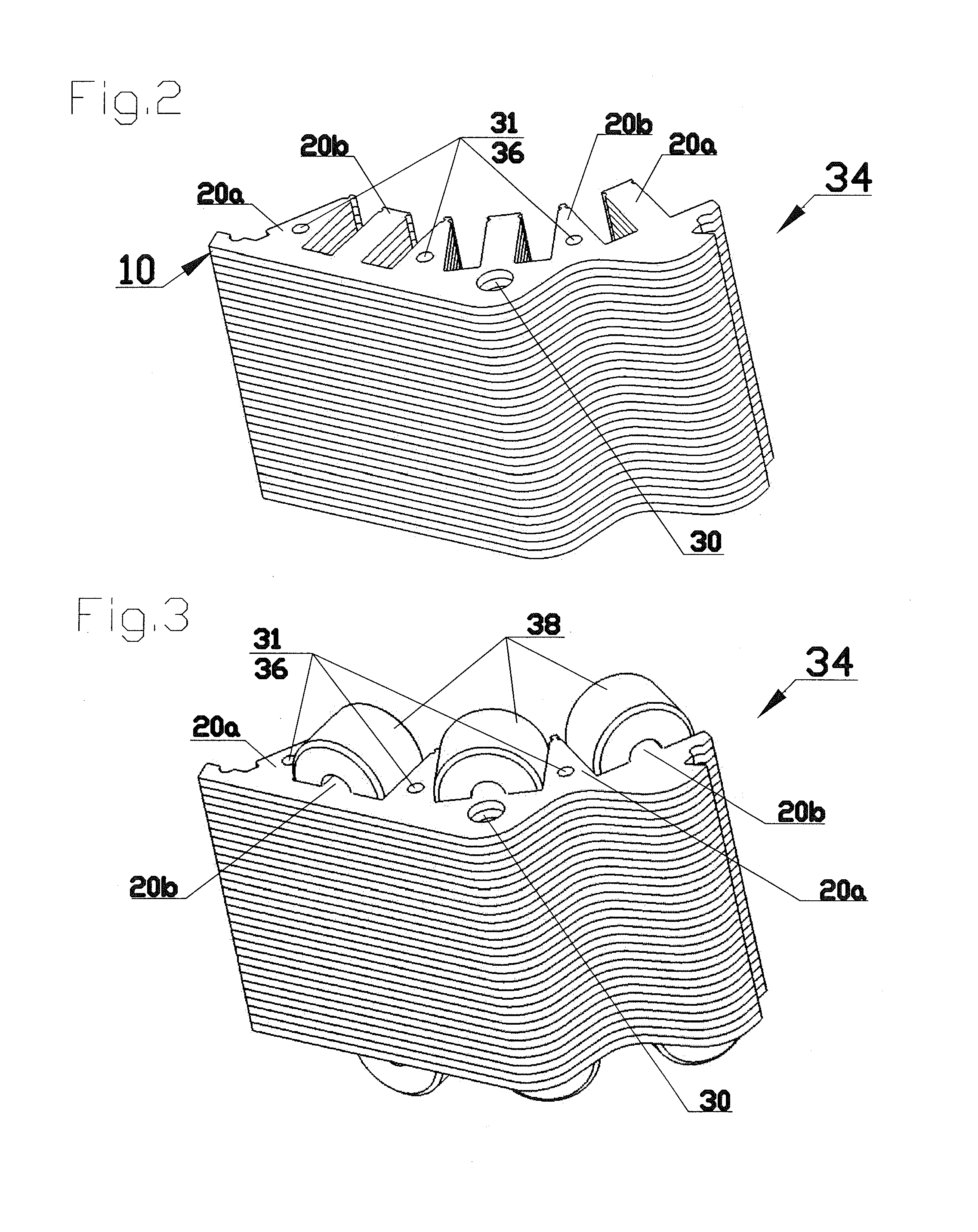
[0050]FIG. 1 shows a topview of a plate segment 10 of a stator for an inner rotor motor 48 of a first embodiment mode of the present invention. The plate segment 10 is a stamped sheetmetal part having an outer side 12, an inner side 14 and two mutually opposite end faces 16 and 18 which together subtend a partly annular geometry. The inner side 14 substantially comprises wedge-shaped protrusions 20a and substantially rectangular protrusions 20b configured alternatingly next to each other. A substantially rectangular recess 22 is present between, i.e. separates, the protrusions 20a and 20b. Each protrusion 20b together with the two adjoining recesses receives on a coil array as elucidated further below in relation to FIG. 3.

[0051]Notches 24 are subtended near the ends of each protrusion 20a, 20b pointing to the inner side 14, each notch 24 of a protrusion 20a being associated to an opposite notch 20b of a protrusion 20b. In the installed state of a plurality of the plate segments 10 ...

second embodiment

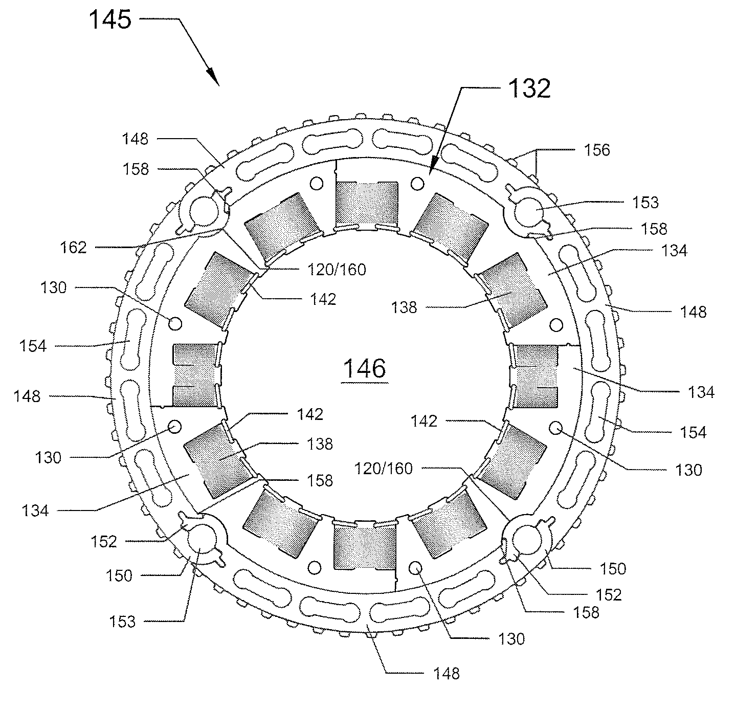
[0063]FIG. 10 shows a topview of a plate segment 110 for a stator 132 of a second embodiment mode of the present invention.

[0064]The plate segment 110 is a stamped sheetmetal part having an outer side 112, an inner side 114 and two mutually opposite end faces 116 and 118 which between them subtend a partly annular shape. The outer side 112 is in the form of an arc of circle fitted with an arcuate indentation 120 constituting one part of rotation-suppressing means which is elucidated further below. The inner side 114 also is substantially in the form of an arc of circle, and just as does the plate segment 10 of the first embodiment mode, it is fitted with a set of nearby protrusions 121a and 121b and, between said protrusions, further with recesses 122, the protrusions 121a and the recesses 122 adjacent to them receiving coil arrays 138 as already shown in FIG. 3 in relation to the invention's first embodiment mode.

[0065]Near the inner side 114, each recess 122 is fitted with mutuall...


PUM

PropertyMeasurementUnit
Fractionaaaaaaaaaa
Dimensional stabilityaaaaaaaaaa
Diameteraaaaaaaaaa

Abstract

A stator (32, 132, 232) or rotor for an electrodynamic machine, in particular for a torque motor acting as an internal or external rotor, comprises a plurality of partly annular plate segments (10, 110, 210) which are stacked in a manner to constitute several partly annular plate segment blocks (34, 134, 234). Combined into a ring, said blocks constitute the stator (32, 132, 232) or rotor the particular adjacent plate segment blocks (34, 134, 234) being mutually clamped by a clamping means. This clamping means already may be integrated into said plate segment blocks or it may be constituted by a housing (145, 245) of which the segments (148, 248) can be clamped against one another. If illustratively the housing (145) is emplaced externally around the stator (132) then the inside diameter of said housing may be varied during installation of the stator (132) or rotor in a manner that the housing may be positioned around the installed plate segment blocks (34, 134) and also may be radially clamped against them.

Description

FIELD OF INVENTION[0001]The present invention relates to a rotor or stator for an electrodynamic machine, in particular for a torque motor, said rotor or stator being fitted with a plurality of stacked, partly annular plate segments which together constitute a ring of annular segments in which coil arrays may be received. This invention moreover relates to a method for manufacturing such a rotor or stator as well as an electrodynamic machine fitted with such a rotor or stator.BACKGROUND ART[0002]Stators and rotors composed of a plurality of plate segments receiving coil arrays are known in the state of the art. For simplicity, only stators are considered below, though the designs of course apply as well to rotors.[0003]Conventionally stators are made of a plurality of partly annular plate segments. These partly annular plate segments are stamped out of sheetmetal and then combined and stacked into rings. The plate segments are offset from one another to stabilize the generally unsta...

Claims


Application Information

Patent Timeline
IPC IPC(8): H02K1/06H02K15/02H02K5/00H02K1/14
CPCH02K1/148Y10T29/49012Y10T29/49009
Inventor MEIER, HANSSCHEICH, HUBERTISERT, HUGO
Owner HANS MEIER
Why Eureka
Try Eureka