
Electromotive coil with improved conductor packing ratio

a technology of conductor and coil, applied in the direction of windings, contact member manufacturing, cable junctions, etc., can solve the problems of limiting the maximum speed of any motor, affecting the shape of the conductor, and affecting the power loss of the conductor, so as to reduce the electrical resistance, reduce the induced eddy current loss, and the effect of the lowest electrical resistan

Inactive Publication Date: 2014-01-28
YANKIE GREALD W +1
View PDF12 Cites 3 Cited by
  • Summary
  • Abstract
  • Description
  • Claims
  • Application Information

AI Technical Summary

Benefits of technology

This invention is a motor coil that uses a special construction called ironless core and slotless, which reduces electrical resistance and induces less loss. The coil is made using rectangular copper wire that is pre-coated and made into a shortened turn within the motor coil using a unique connection method. The tight packing arrangement of the electrical current conductors results in a dense copper packing factor, which is not possible with round magnet wire. This invention allows for a more efficient and effective motor coil construction.

Problems solved by technology

Motor coil construction and coil conductor shape impacts power losses in the coil called Eddy Current Losses resulting from a magnetic field sweeping the conductors.
This loss is an exponential function of the frequency and limits the maximum speed of any motor.
This creates excessive length in the end-turn thereby increasing the electrical resistance of the coil.
Making a shortened end turn will decrease the resistance of the circuit relative to round wire construction.
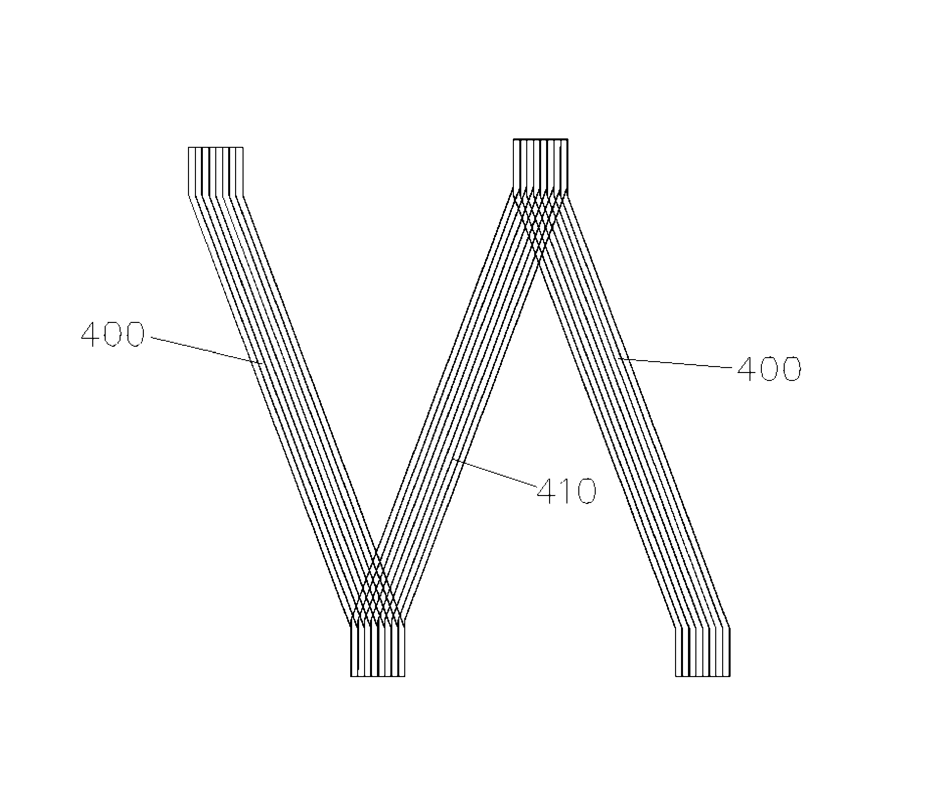
The geometry of round magnet wire does not allow for the high packing factor as compared to the rectangular wire shown in FIG. 10, which results in over 50% more copper in the magnetic field compared with round magnet wire in the same space.
Square wire and round wire can be manufactured in this manner to provide some improved motor performance benefits but motor performance will not be optimal. FIG. 8 is an illustration depicting Eddy Currents in Conductors within a magnetic field.
The circulating currents generate heat within the conductors reducing the performance of the motor.

Method used


Image

  • Electromotive coil with improved conductor packing ratio
  • Electromotive coil with improved conductor packing ratio
  • Electromotive coil with improved conductor packing ratio

Examples


Embodiment Construction

[0067]The electromotive coil construction is made using insulated rectangular wire cut into individual segments 102 and formed to fit as required by the electromotive device design. Here described is the construction of a Permanent Magnet Brushless Stator, as used in a slotless or ironless coil linear motor construction.

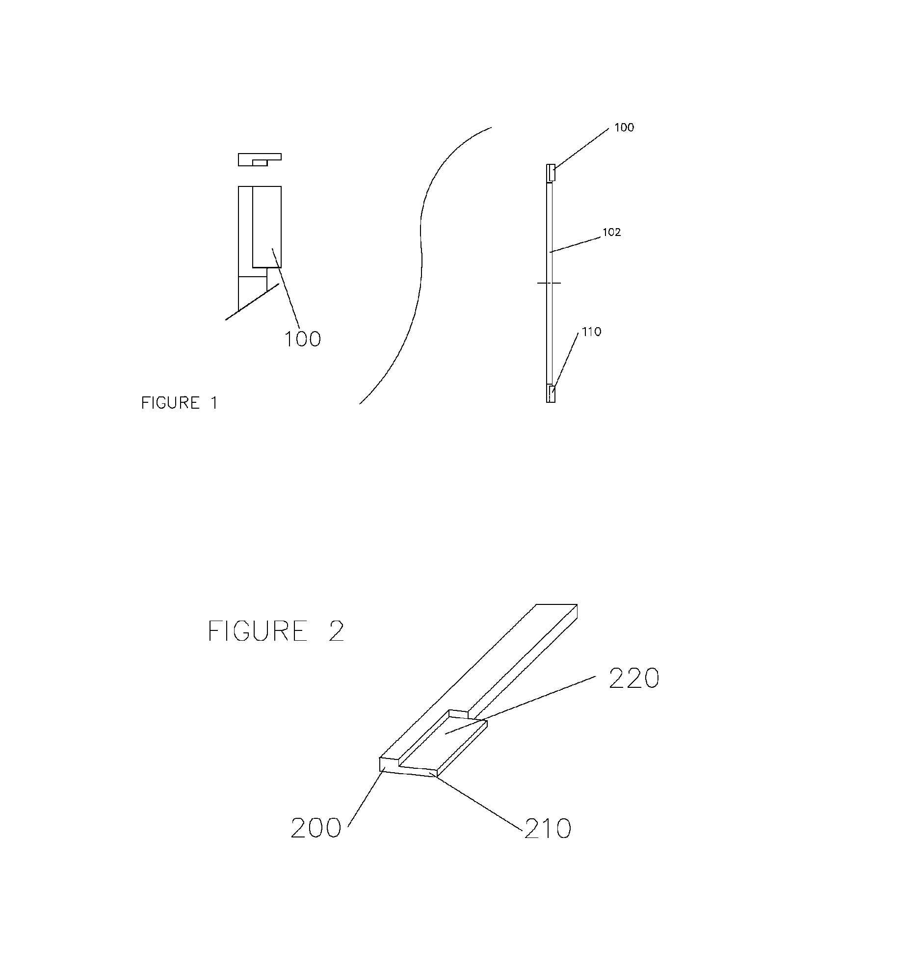
[0068]FIG. 1 shows the individual electric current conductors formed to the length required and each end of the conductors 102 formed for joining at a later sequence.

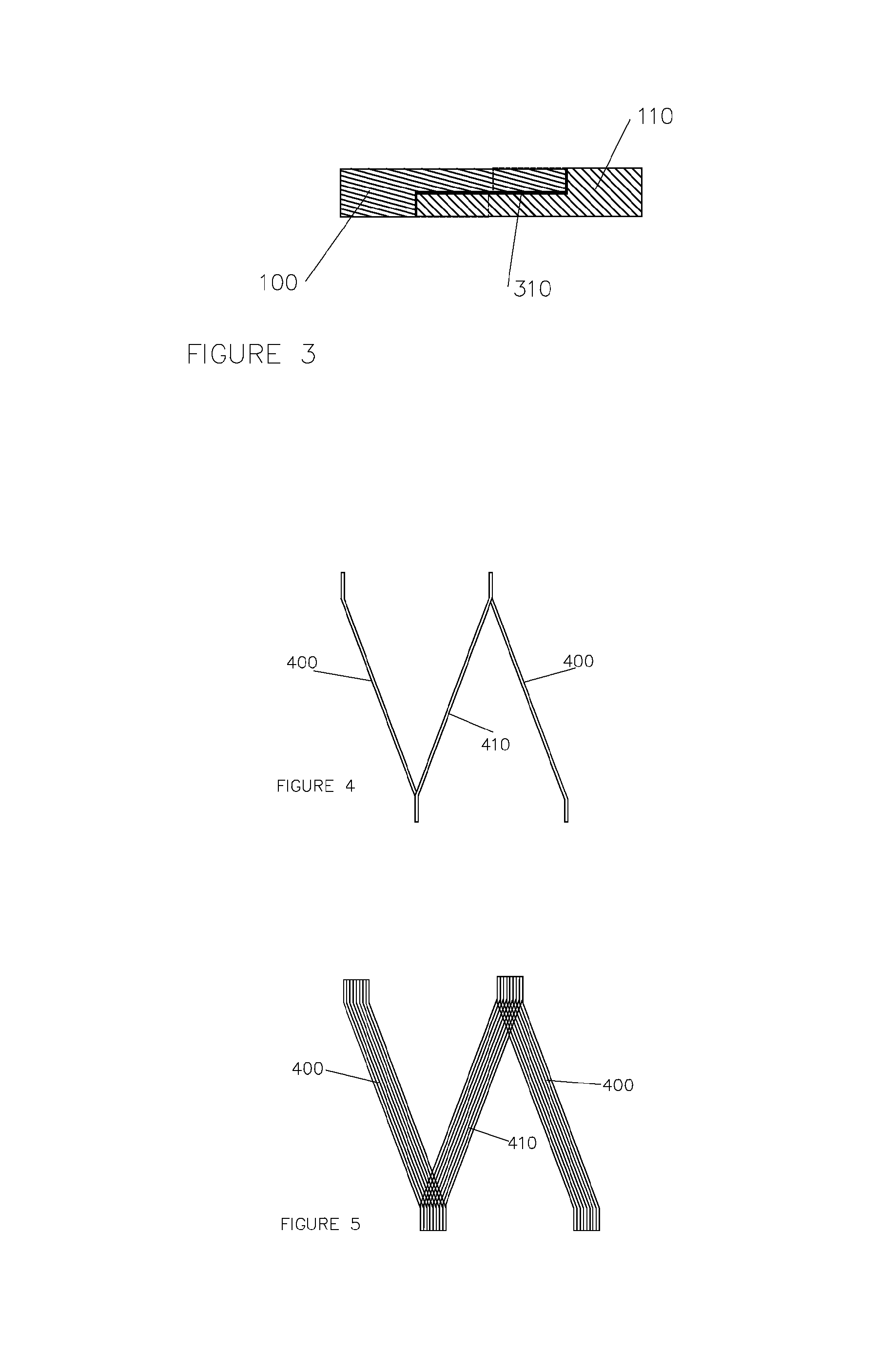
[0069]FIG. 2 shows the conductor end mechanically formed in a forming tool, detail end view only. The end of each conductor has a feature described as item 200, 210 and 220 mechanically formed into each end of the conductor 102 to enable nesting of two mating conductors. The insulation is removed from the area of mechanical forming to ensure a clean area for the mating and bonding surfaces. Each end of conductor 102 is mechanically formed to create a nesting feature to enable nesting of two mating electr...


PUM

PropertyMeasurementUnit
Fractionaaaaaaaaaa
Fractionaaaaaaaaaa
Weightaaaaaaaaaa

Abstract

The disclosed invention describes a motor / generator coil produced using rectangular electric current conductors of any thickness and width. A unique joint between the up and down segments of the coil turn enables an improved conductor packing ratio and geometrical orientation that minimizes the effect of eddy currents. The resulting coil produces higher power than typical wire wound motors but is lighter weight and physically smaller in size. In addition, the coil can be free-standing, and is capable of slotless and / or ironless core device configuration.

Description

BACKGROUND[0001]Permanent Magnet Motors, Electronically Commutated Motors, Coreless, Ironless Core, Slotless, DC Brush, radial and linear electric motors and generators manufactured today typically use round magnet wire to produce the electrical current path within the electromotive coil winding. The circular shape of round magnet wire limits the amount of current carrying conductive copper that can be fit into a given volume. Motor designers strive to achieve conductor configurations that maximize the amount of copper in the magnetic field of the motor stator or armature to enhance motor performance. Motor coils with higher conductor packing-factor or slot-fill ratios exhibit better overall performance than coils with lower packing-factor or slot-fill ratios.[0002]An electric motor coil construction for either armature or stator that maximizes the amount of conductors within the magnetic gap of the rotor decreases the electrical resistance of the circuit within the motor. As an ele...

Claims


Application Information

Patent Timeline
IPC IPC(8): H02K3/04
CPCH02K3/04Y10T29/49218Y10T29/49204Y10T29/49222
Inventor YANKIE, GREALD WGRAHAM, GREGORY S
Owner YANKIE GREALD W
Learn More