Wind turbine including optical sensor system

a sensor system and wind turbine technology, applied in the direction of motors, engine fuctions, sustainable buildings, etc., can solve the problems of recurring operational problems, lightning conductors that cannot protect sensor equipment mounted on or in wind turbine components, and sensor systems incorporating metallic components such as wiring and circuits are particularly susceptible to damage, so as to minimise turbulence and maximise the output power of the wind turbine

Inactive Publication Date: 2014-11-11
VESTAS WIND SYST AS
View PDF10 Cites 5 Cited by
  • Summary
  • Abstract
  • Description
  • Claims
  • Application Information

AI Technical Summary

Benefits of technology

[0057]Systems of wind turbines according to the second aspect of the invention allow the aerodynamic interaction of the blade with the air flow to be monitored in real time, and for the blade to be adjusted as desired based on a measure of turbulence.
[0058]In certain preferred embodiments of wind turbines according to the second aspect of the invention, the aerodynamic par

Problems solved by technology

Due to the height of most wind turbines, damage from lightning strikes is a recurring operational problem.
However, lightning conductors will not always adequately protect sensor equipment mounted on or in wind turbine components.
Sensor systems incorporating metallic components such as wiring and circuits are particularly susceptible to damage from an electrical discharge.
Additionally, the operation of sensor systems in a wind turbine may be adversely affected by the magnetic and electrical fields associated with heavy electrical and mechanical machinery present, for example in the nacelle.
As a result, the sensor systems are not able to work in an optimal way.
The known optical microphones have not typically performed as well as traditional electrical micro

Method used


Image

  • Wind turbine including optical sensor system
  • Wind turbine including optical sensor system
  • Wind turbine including optical sensor system

Examples


Embodiment Construction

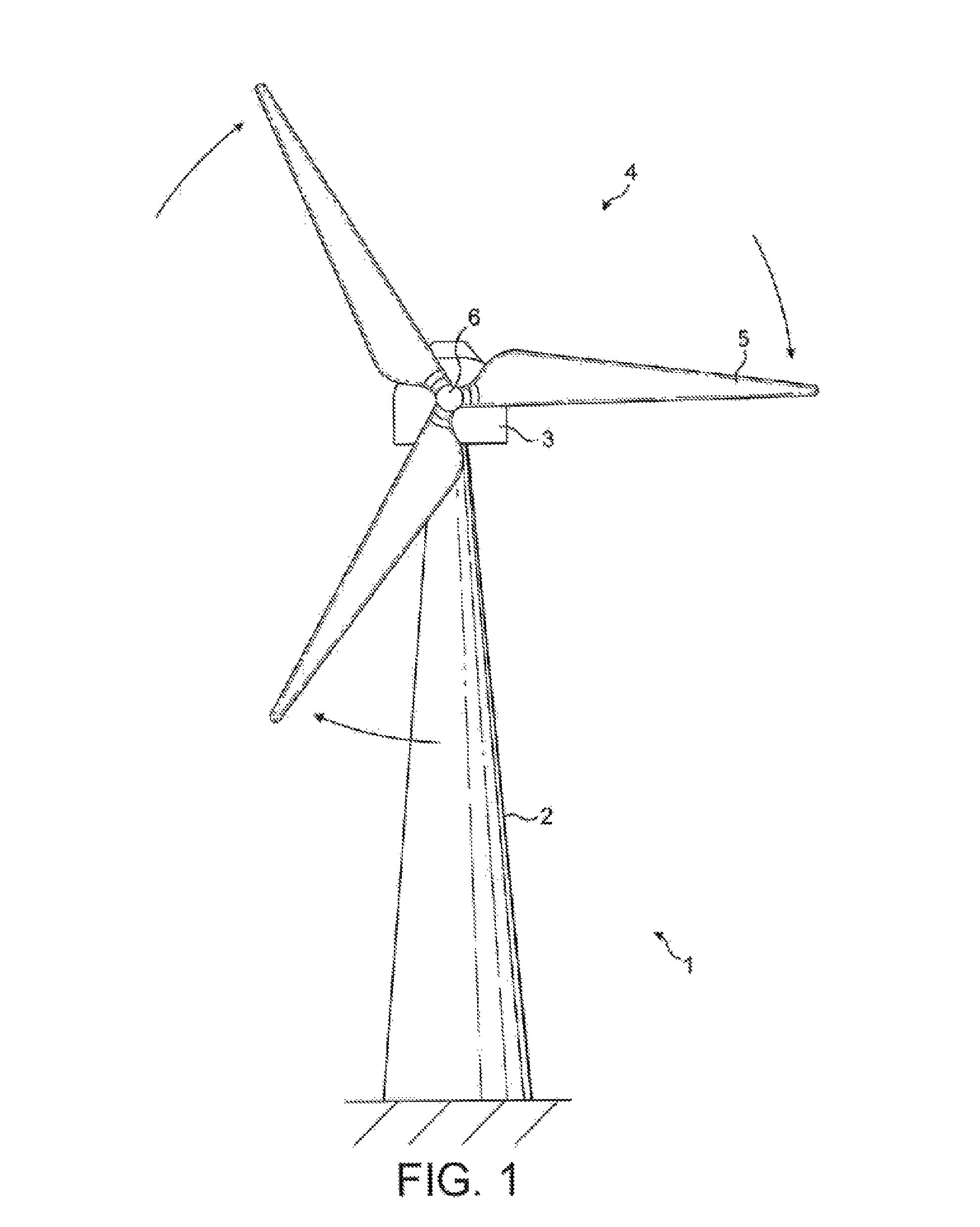
[0080]FIG. 1 illustrates a wind turbine 1 according to the invention comprising a wind turbine tower 2 on which a wind turbine nacelle 3 is mounted. A wind turbine rotor 4 comprising three wind turbine blades 5 is mounted on a hub 6. The hub 6 is connected to the nacelle 3 through a low speed shaft (not shown) extending from the nacelle front. The wind turbine of FIG. 1 may be a small model intended for domestic or light utility usage, or may be a large model such as those that are suitable for use in large scale electricity generation on a wind farm. In the latter case, the diameter of the rotor may be as large as 100 meters or more.

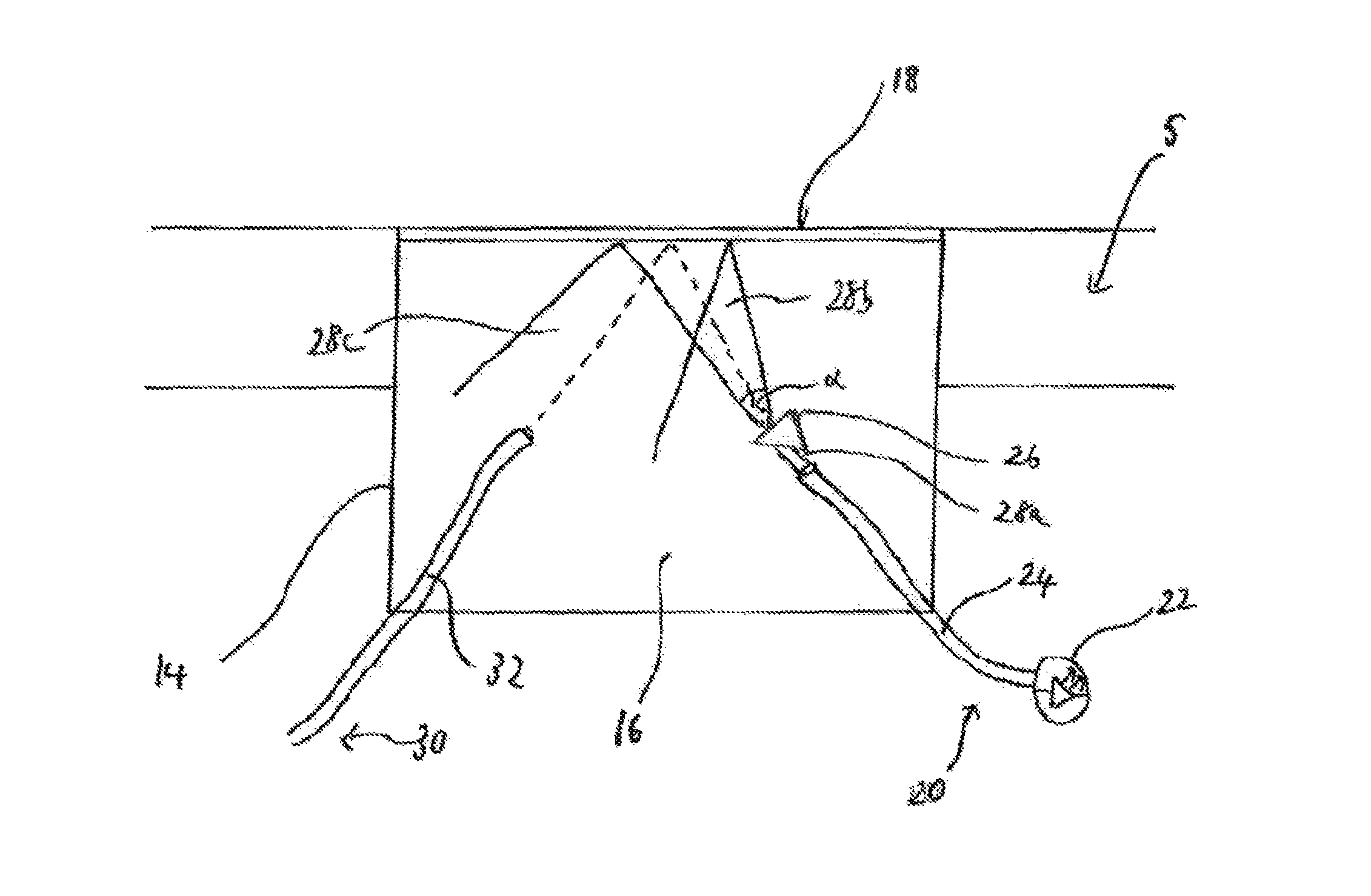
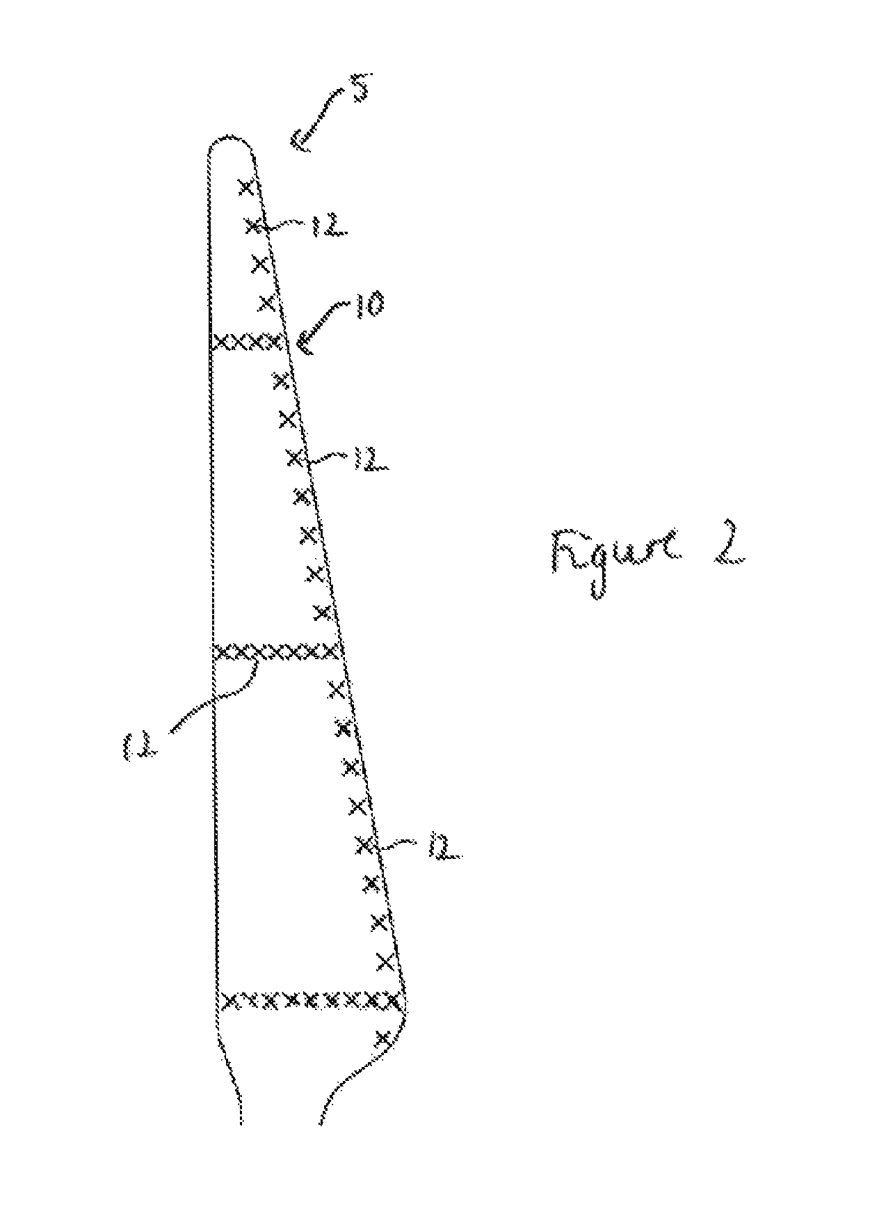
[0081]Each wind turbine blade 5 incorporates a sensor system 10 comprising a plurality of turbulence sensors 12 spaced apart along the blade, as illustrated in FIG. 2 which shows a view of the leeward side of the blade 5. Turbulence sensors 12, as described in more detail below, are disposed along the surface of the blade 5 at a plurality of locations. ...


PUM


Abstract

A wind turbine includes an optical sensor system comprising one or more optical sensors comprising: a sensor membrane; a light source for illuminating a surface of the sensor membrane; an optical dispersive element arranged to disperse the light from the light source; and a light detector for receiving a portion of the dispersed light beam after reflection from the surface of the sensor membrane and dispersion of the light beam by the optical dispersive element. The wavelength of the light received at the light detector varies as a function of the displacement of the sensor membrane and the light detector operatively provides an output based on changes in the wavelength of the received light. The wind turbine is operable based on an input to a wind turbine control system received from the optical sensor system.

Description

[0001]The present invention relates to an optical sensor system for a wind turbine and to a wind turbine incorporating such a sensor system. The invention finds particular application in the detection of turbulence or in the monitoring of vibration of a wind turbine component.BACKGROUND OF THE INVENTION[0002]In order to optimise the extraction of energy from the wind, wind turbines are typically equipped with a number of sensor devices, which may provide feedback to the control systems of the turbine. For example, sensor devices are commonly used for monitoring environmental conditions at the wind turbine as well as for measuring parameters of the wind turbine components, such as strain. Using the data obtained from these sensor devices, the wind turbine may be operated accordingly, such as controlling the pitch of the blades. Also the yaw of the nacelle, can be adjusted in order to make the wind turbine as efficient as possible at generating energy.[0003]Sensor devices are also com...

Claims


Application Information

Patent Timeline
IPC IPC(8): G01H9/00F03D11/00F03D7/00G01N21/55
CPCF03D11/0091F05B2270/804G01H9/00F03D7/00Y02E10/722G01N21/55Y02B10/30F05B2260/80F03D17/00Y02E10/72
Inventor OLESEN, IB, SVEND
Owner VESTAS WIND SYST AS
Why Eureka
Try Eureka