
Induction heating device, control method thereof, and control program thereof

a technology of induction heating and control method, applied in induction heating, electric/magnetic/electromagnetic heating, induction current sources, etc., can solve the problems of furnace itself being sometimes dissolved, waste caused, central portion becoming at a high temperatur

Active Publication Date: 2014-11-18
MITSUI E&S MACHINERY CO LTD
View PDF8 Cites 3 Cited by
  • Summary
  • Abstract
  • Description
  • Claims
  • Application Information

AI Technical Summary

Benefits of technology

The present invention allows for the optimal operation of the part that produces the most power. This is done by using multiple induction heating coils and inverters that work together in a way that reduces the needed rating of the conversion device. This is achieved by controlling the minimum phase angle, which causes a resonant current flow through each coil. Ultimately, this results in a more efficient and effective system for producing power.

Problems solved by technology

Before finishing various products by performing forging, rolling or extrusion against a billet (ingot), it is necessary to soften the billet by heating it, for example, to a settling temperature 1250° C. When an attempt is made to keep a rod-shaped billet at a settling temperature by heating a single coil, as a temperature distribution becomes non-uniform, it often results in a waste caused by a failure that it does not become at a predetermined temperature in a transient time such as during a standby mode and when transitioning from a standby mode to normal heating mode.
Further, when an attempt is made to keep both end portions at a settling temperature, the central portion becomes at a high temperature and the furnace itself is sometimes dissolved.
Therefore, each of the inverters is operated in parallel via mutual inductance and it may cause a mutual power transfer between the inverters when having a mutual phase shift of electric current between the inverters.

Method used


Image

  • Induction heating device, control method thereof, and control program thereof
  • Induction heating device, control method thereof, and control program thereof
  • Induction heating device, control method thereof, and control program thereof

Examples


first embodiment

[0043]Overall Configuration:

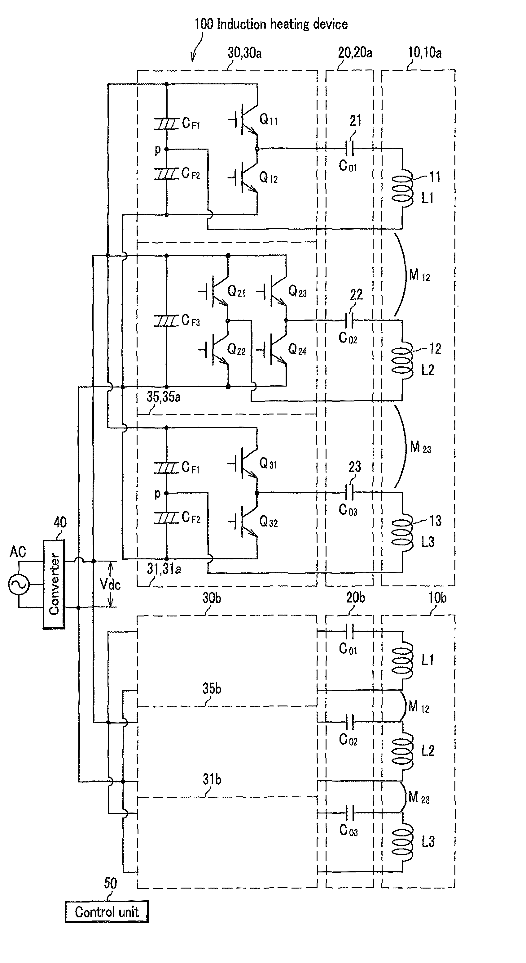
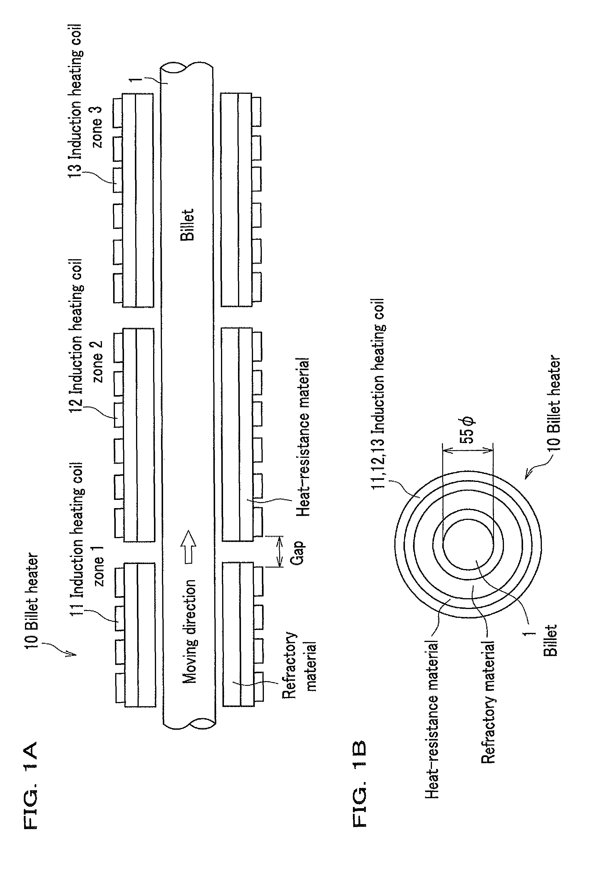
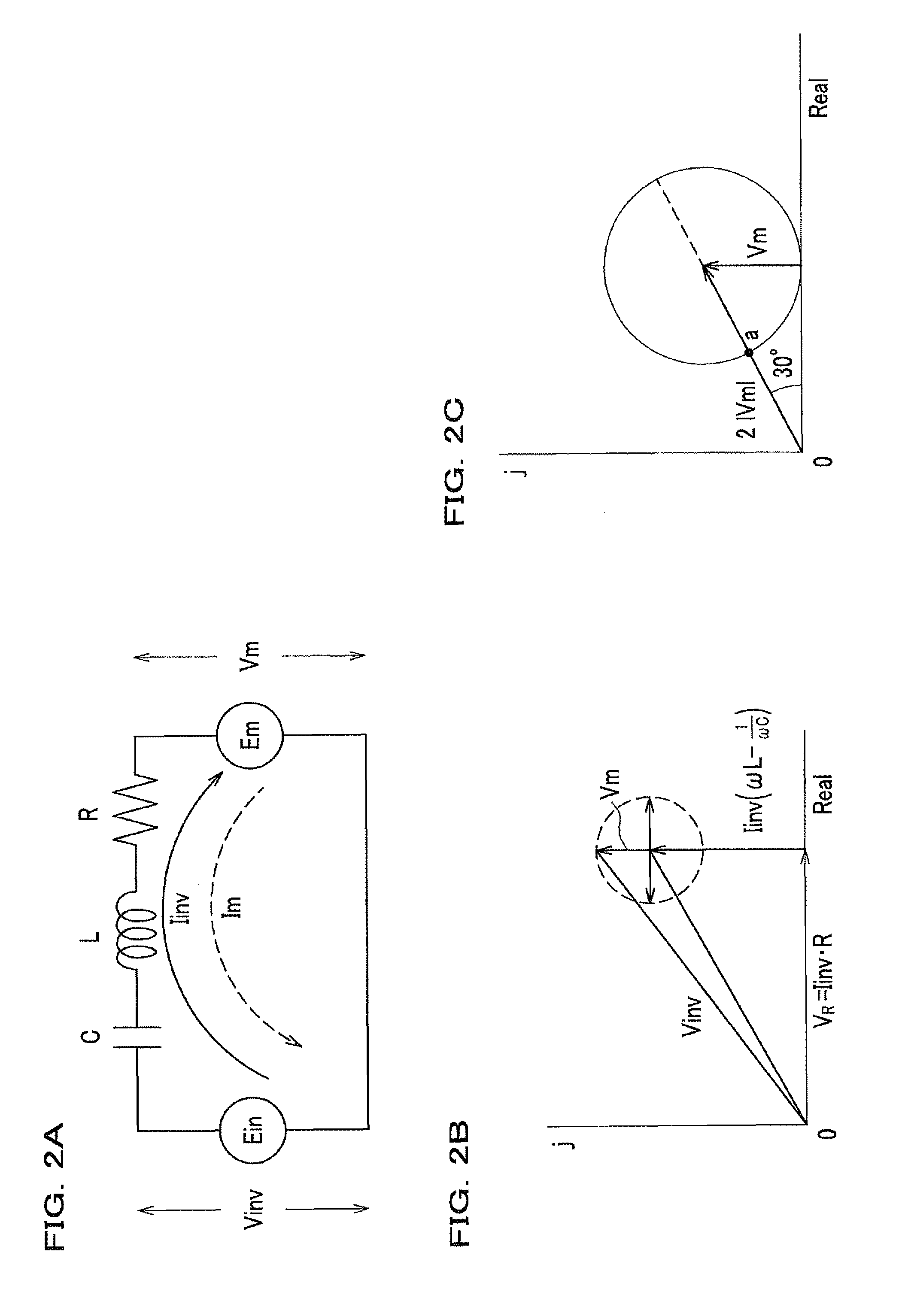
[0044]FIGS. 1A and 1B are structural drawings of a billet heater used in an induction heating device according to an embodiment of the present invention, FIG. 2A is an equivalent circuit diagram of the billet heater, FIGS. 2B and 2C are vector diagrams for explaining an operation, and FIG. 3 is a circuit diagram of the induction heating device according to an embodiment of the present invention.

[0045]As shown in FIGS. 1A and 1B, a billet heater 10 is provided with a refractory material and a heat-resistant material, each of which has a concentric shape around a columnar billet 1 (ingot) to be heated, and configured with an induction heating coil wound on the surface of the outer periphery of the heat-resistance material. The refractory material and the heat-resistance material are intended to avoid heat radiation of the billet, which is heated to a high temperature, as well as to prevent coil wires from being fused. Note that the diameter of the billet 1 ...

second embodiment

[0108]The first embodiment is configured with independent circuits, using half-bridge circuits in the inverters 30 and 31, and a full bridge circuit in the inverter 35, but in case of a three-zone configuration, zones can be connected in parallel using a three-phase IPM (Intelligent Power Module) module.

[0109]FIG. 10 is a circuit diagram of an inverter and a billet heater using an IPM module.

[0110]An IPM module is generalized for the purpose of driving a three-phase motor, by modularizing six IGBTS and six commutation diodes. An IPM module 60 includes a power supply terminals V+, V−, output terminals U, V, W, and a gate terminal.

[0111]An induction heating device 101 is configured with three half-bridge circuits, using an IPM module 60, for three induction heating coils 11, 12, 13, respectively, where electrolytic capacitors CF1, CF2 in series connection are connected to both ends of the power supply terminals V+, V−, and the DC voltage Vdc is applied thereto. Each of the output term...

third embodiment

[0113]The second embodiment uses a single IPM module, but two or more IPM modules can be connected in parallel to increase a capacity of a conversion device.

[0114]FIG. 11 is a circuit diagram of inverters and peripherals of a billet heater, using IPM modules.

[0115]An induction heating device 102 includes two IPM modules 60a and 60b, electrolytic capacitor CF1 and CF2, capacitors 24a, 25a, 26a, capacitors 27, 28, 29, capacitors 24b, 25b, 26b, and induction heating coils 11, 12, 13.

[0116]Electrolytic capacitors CF1 and CF2 in series connection are connected to both ends of the power supply terminals V+ and V− of each of the IPM modules 60a and 60b, and the DC voltage Vdc is applied thereto. Each of output terminals U1, V1, W1 of the IPM module 60a is connected to one end of each of the capacitors 24a, 25a, 26a, the other end thereof is connected to one end of each of the induction heating coils 11, 12, 13 and one end of each of the capacitors 24b, 25b, 26b, the other end of each of th...


PUM


Abstract

The present invention includes: a plurality of induction heating coils (11, 12, 13) which are disposed adjacently; capacitors (21, 22, 23) each of which is connected in series thereto; a plurality of inverters (30, 35, 31) each of which applies a high frequency voltage converted from a DC voltage to each series resonant circuit of the induction heating coil and the capacitor; and a control circuit (50) which operates the plurality of the inverters with a same frequency and current synchronization, controls so that a phase difference becomes minimal at a specific inverter, which supplies the maximum power to the plurality of the induction heating coils, between the high frequency voltage generated therefrom, and a resonant current flowing the series resonant circuit, and set a DC power supply voltage Vdc applied to the plurality of the inverters so that the output voltages (Vinv) become greater than mutual induction voltages (Vm).

Description

CROSS REFERENCE TO RELATED APPLICATION[0001]This present application is a National Stage Application of PCT Application No. PCT / JP2011 / 075251 filed on Nov. 2, 2011, which claims benefit of Ser. No. 2011-063528, filed Mar. 23, 2011 in Japan and which applications are incorporated herein by reference. To the extent appropriate, a claim of priority is made to each of the above disclosed applications.TECHNICAL FIELD[0002]The present invention relates to an induction heating device, provided with inverters for supplying a high frequency power to induction heating coils, a control method thereof, and a control program thereof.BACKGROUND OF THE INVENTION[0003]Before finishing various products by performing forging, rolling or extrusion against a billet (ingot), it is necessary to soften the billet by heating it, for example, to a settling temperature 1250° C. When an attempt is made to keep a rod-shaped billet at a settling temperature by heating a single coil, as a temperature distributio...

Claims


Application Information

Patent Timeline
Patent Type & Authority Patents(United States)
IPC IPC(8): H05B6/02H05B6/12H05B6/64H05B6/06H05B6/10
CPCH05B6/02H05B6/06H05B6/101H05B6/10H05B6/44
Inventor UCHIDA, NAOKIKAWANAKA, KEIJIAO, TAKAHIRO
Owner MITSUI E&S MACHINERY CO LTD
Learn More