Power supply and power supplying system with remote power management function

a technology of power supply and function, applied in the direction of dc source parallel operation, emergency protective arrangements for limiting excess voltage/current, single ac network with different frequencies, etc., can solve the problems of electronic equipment damage, electronic equipment accordingly damaged, and requiring a certain spa

Active Publication Date: 2014-11-25
DELTA ELECTRONICS INC
View PDF15 Cites 5 Cited by
  • Summary
  • Abstract
  • Description
  • Claims
  • Application Information

AI Technical Summary

Benefits of technology

[0011]Another object of the present invention provides a power supply and a power supplying system used for a data-processing system, wherein the power supply and the power supplying system have power protection mechanism and remote power management function, so as to prevent the generation of arc flash due to high electric current flowing through the contacts of the connectors and avoid damages to the power supply or the data-processing equipments due to the electric arc and unintentional or accidental interruption of power-supplying.

Problems solved by technology

For general power conversion systems, power distribution systems, power supplying systems and electronic equipments, an instant spark may be generated at the switch contacts due to the electric current flowing therethrough, and the electric arc between the two contacts will melt the switch contacts, which causes damages to the electronic equipment.
Moreover, in the power supply, when the input plug of an external power source is contacted with or pulled out from the socket of the power supply, an electric arc may also be resulted and the electronic equipment is accordingly damaged.
However, these solutions require a certain space and high cost, and are not suitable to be used for the power supply with high power density.
However, it is still an unsafe protection mechanism to prevent the system from shutting down or damages due to arc flash and unintentional or accidental interruption of power.
However, this method of power management is laboring and inconvenient, and cannot achieve the best power management and distribution, and power protection as well.

Method used


Image

  • Power supply and power supplying system with remote power management function
  • Power supply and power supplying system with remote power management function
  • Power supply and power supplying system with remote power management function

Examples


Embodiment Construction

[0026]The present invention will now be described more specifically with reference to the following embodiments. It is to be noted that the following descriptions of preferred embodiments of this invention are presented herein for purpose of illustration and description only. It is not intended to be exhaustive or to be limited to the precise form disclosed.

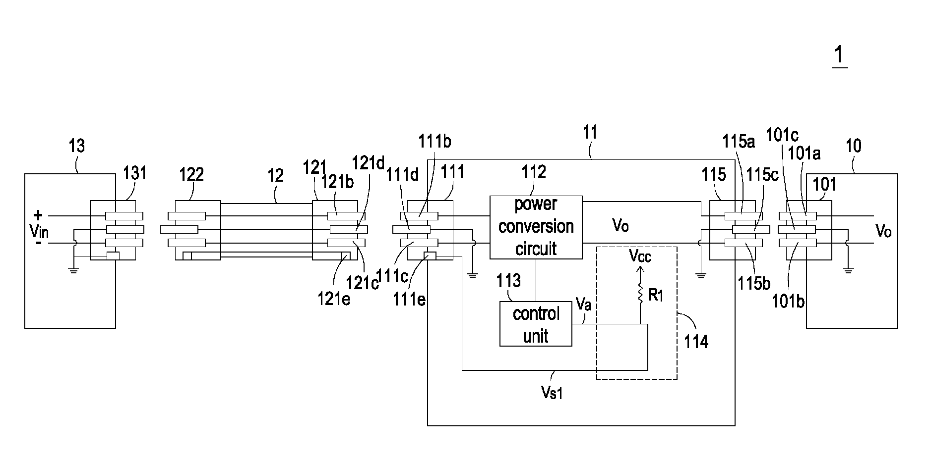
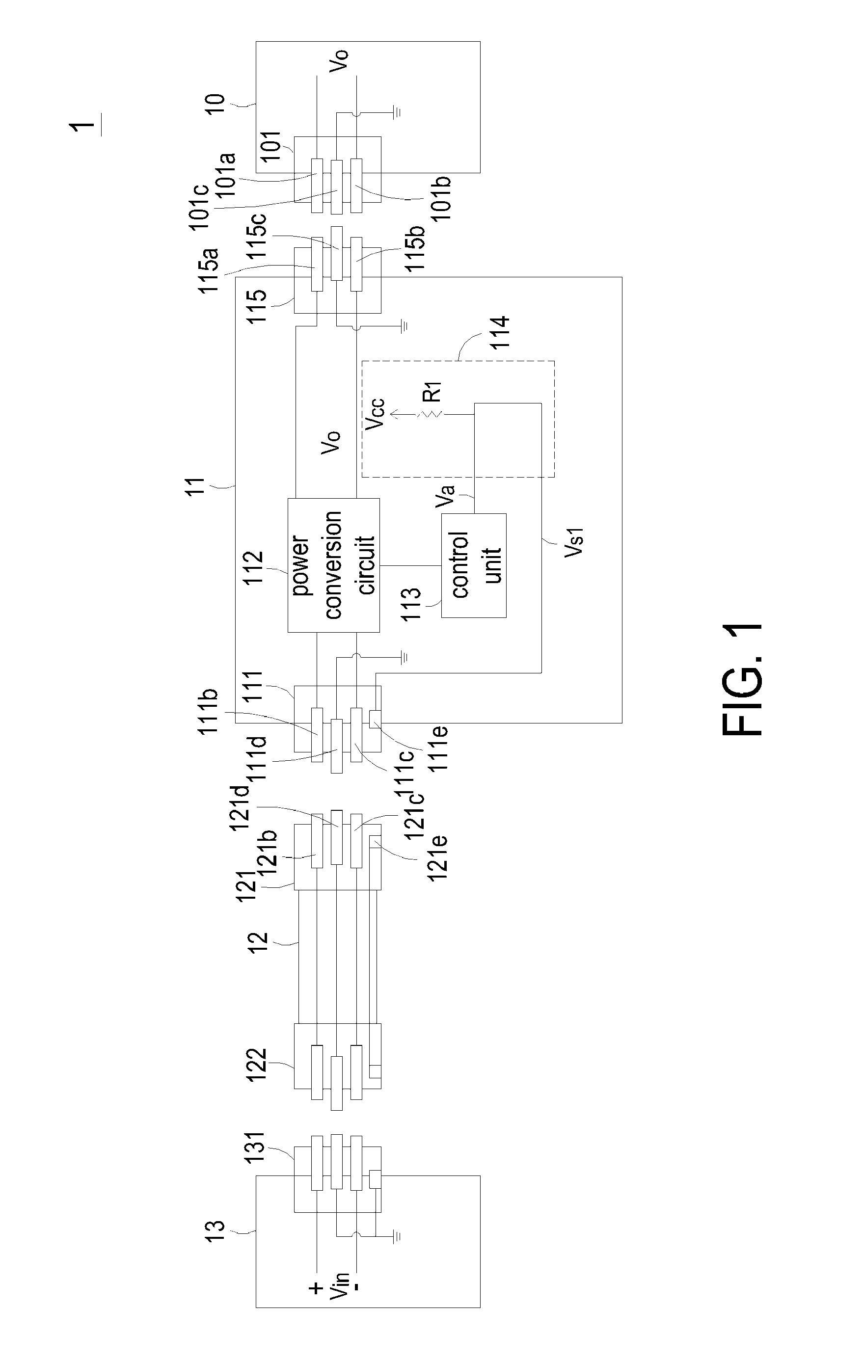
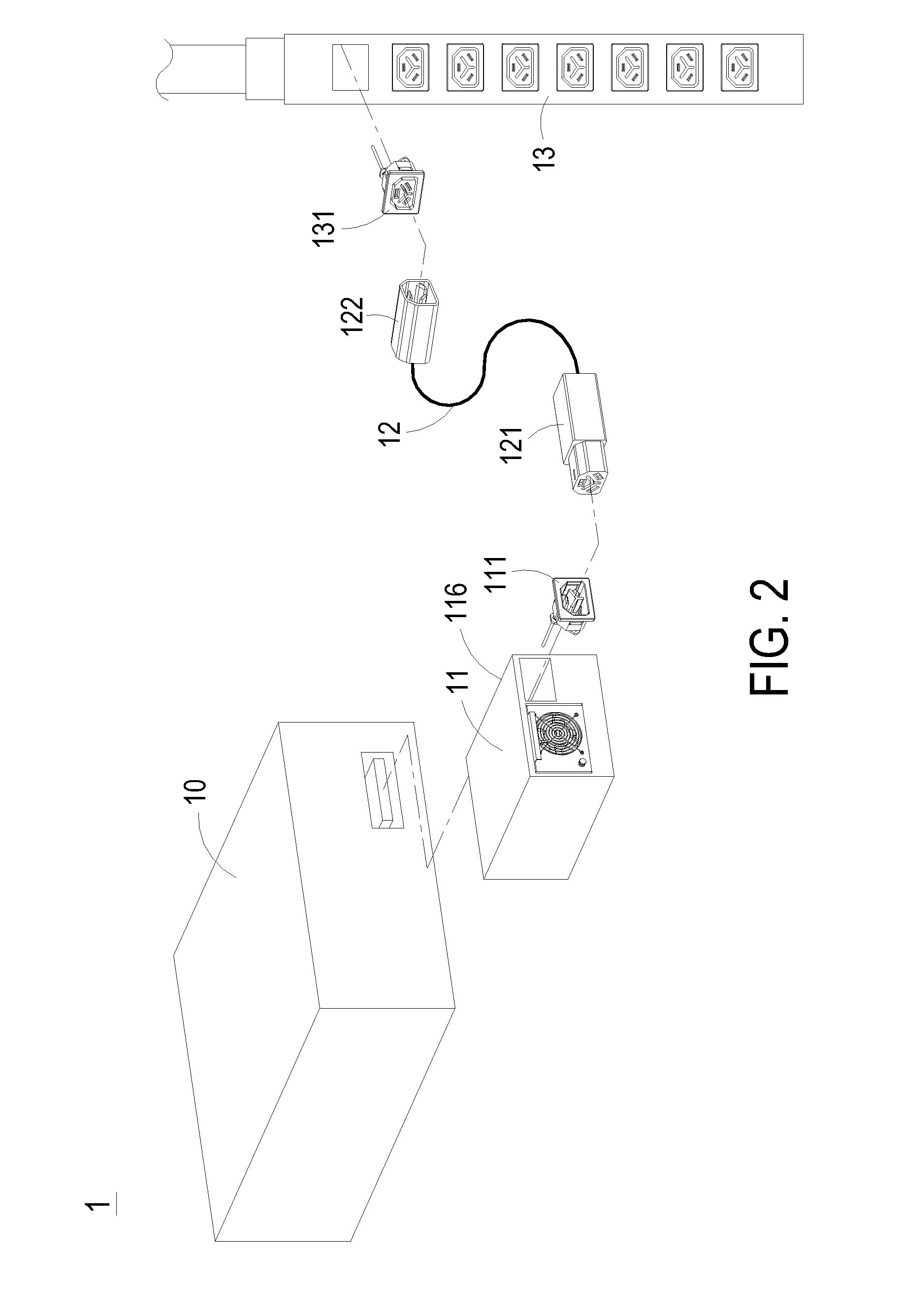
[0027]FIG. 1 is a circuit block diagram showing a power supply used for a data-processing system and having power protection mechanism and remote power management function according to a first preferred embodiment of the present invention; and FIG. 2 is a schematic diagram of FIG. 1 according to the preferred embodiment of the present invention. As shown in FIGS. 1 and 2, the data-processing system 1 comprises one or more data-processing equipments 10, for example one or more servers. The data-processing equipment 10 is electrically coupled with one or more power supplies 11 and supplied power by the one or more power supplies 11...


PUM


Abstract

The power supply includes a first power connector, a power conversion circuit, a control unit and a detection circuit. The first power connector includes a plurality of power terminals and a first detecting terminal. The power conversion circuit is coupled to the power terminals of the first power connector for converting an input voltage into an output voltage. The control unit is coupled to the power conversion circuit for controlling an operation of the power conversion circuit. The detection circuit is coupled to the control unit and the first detecting terminal of the first power connector for detecting if the first detecting terminal is connected or disconnected with a predetermined voltage terminal and correspondingly generating a power transmission status signal to the control unit. When the detection circuit detects the first detecting terminal is disconnected with the predetermined voltage terminal, the power transmission status signal is under a disabled status and the control unit controls the power conversion circuit not to generate or output the output voltage to the load according to the power transmission status signal.

Description

CROSS-REFERENCE TO RELATED APPLICATIONS[0001]This application claims the benefit of prior U.S. provisional application 61 / 263,895, which is entitled “INTELLIGENT POWER CONNECTOR ASSEMBLY CAPABLE OF PREVENTING GENERATION OF ARC FLASH” and filed Nov. 24, 2009, and claims the benefit of prior U.S. provisional application 61 / 266,627, which is entitled “ARC FLASH PROTECTION MECHANISM FOR POWER SUPPLY AND DATA-PROCESSING SYSTEM EMPLOYING SAME” and filed Dec. 4, 2009. This application is a continuation-in-part of U.S. patent application Ser. No. 12 / 713,764 filed on Feb. 26, 2010, and entitled “POWER SUPPLY WITH ARC FLASH PROTECTION MECHANISM AND DATA-PROCESSING SYSTEM EMPLOYING SAME”. The entire disclosures of the above applications are all incorporated herein by reference.FIELD OF THE INVENTION[0002]The present invention relates to a power supply and a power supplying system, and more particularly to a power supply and a power supplying system with remote power management function used fo...

Claims


Application Information

Patent Timeline
Patent Type & Authority Patents(United States)
IPC IPC(8): H02J7/22H02H3/00H02H9/00H01H31/34
CPCH02H9/004H02H3/00Y10T307/826Y10T307/25Y10T307/505Y10T307/469Y10T307/297
Inventor HUANG, YU-HUNG
Owner DELTA ELECTRONICS INC
Why Eureka
Try Eureka